Induction signal control method for ring-shaped intersection

A roundabout and induction signal technology, applied in the direction of traffic signal control, can solve problems such as increased vehicle delay, traffic disorder, and traffic accidents, and achieve the effects of reducing delays, relieving traffic congestion, and improving traffic safety

Inactive Publication Date: 2012-08-15
JIANGSU UNIV
View PDF0 Cites 0 Cited by
  • Summary
  • Abstract
  • Description
  • Claims
  • Application Information

AI Technical Summary

Problems solved by technology

[0002] At present, the status quo of urban traffic is that no vehicle detectors and induction control signal lights are installed at roundabouts. Therefore, with the increase of urban traffic volume, roundabouts are increasingly unable to meet the needs of vehicles, mainly reflected in: (1 ) When the vehicles entering the ring do not obey the traffic rules and give way to the vehicles around the ring, it will cause traffic disorder and cause traffic accidents; (2) The capacity of conventional roundabouts is limited by each weaving section, and cannot The number of lanes and the number of lanes of the ring road can effectively improve the traffic capacity, resulting in insufficient traffic capacity; (3) Although the timing signal control of the roundabout can improve the traffic capacity of the roundabout in practice, due to the urban traffic flow Arrival is often random, and an inherent defect of using timing control is that it is difficult to match the signal timing with the arrival of traffic flow, which often results in the waste of green light resources and the increase of vehicle delays

Method used


Image

  • Induction signal control method for ring-shaped intersection
  • Induction signal control method for ring-shaped intersection
  • Induction signal control method for ring-shaped intersection

Examples


Embodiment Construction

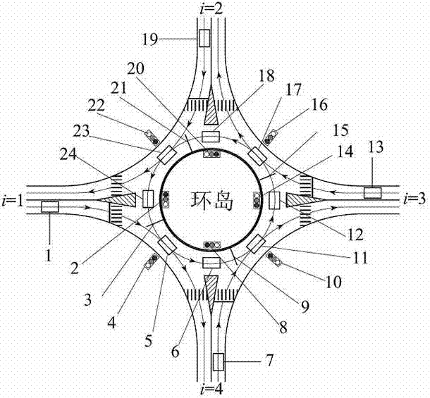
[0018] as attached figure 1 The roundabout (or roundabout) shown, with four entry and exit roads i , that is, the import and export roads i =4. figure 1 The arrow lines in the figure indicate the direction of traffic flow. In addition to setting motor vehicle parking lines in front of the crosswalks of the four entrance roads, it is also necessary to set the first, second, and third lanes in front of the intersection and conflict points of the ring roads of the four entrance roads. , the fourth ring road stop line 3, 9, 15, 21, in the rear of these four ring road stop lines 3, 9, 15, 21 correspondingly set the first, second, third . The fourth looping vehicle arrival detection coils 24 , 6 , 12 , 18 are used to detect the arrival of the looping vehicle. The first, the second, the third, the fourth ring road vehicle queuing detection coils 23, 5, 23, 5, 11, 17, for detecting the occurrence of queuing vehicles around the circle. The first, second, third, and fourth vehicle ...


PUM


Abstract

The invention discloses an induction signal control method for a ring-shaped intersection, comprising the following steps of: setting a ring circling vehicle arrival detection coil, a ring entering and ring surrounding vehicle queuing detection coil and a ring circling induction signal lamp at the ring-shaped intersection; judging whether the arrival of the following ring circling vehicles is detected by the ring circling vehicle arrival detection coil within ring circling vehicle preliminary green light time, if not, transforming phase, setting ring entering vehicle preliminary green light time, if so, judging whether the queuing vehicle is detected by the ring entering vehicle queuing detection coil; if no queuing vehicle is detected by the ring entering vehicle queuing detection coil, prolonging ring circling green light interval time, and if the queuing vehicle is detected by the ring entering vehicle queuing detection coil, transforming the phase, and providing ring entering preliminary green light time. With the control method, the priority of the ring circling vehicles can be ensured, when the vehicle queue is too long, benefits of the ring circling vehicles and the ring entering vehicles can be balanced, so that the control method is suitable for random arrival of the traffic, and can thoroughly settle the conflict between the ring entering vehicles and the ring circling vehicles, reduce delay of the traffic, alleviate traffic jams and improve traffic safety.

Description

technical field [0001] The invention belongs to the field of urban road traffic control, and relates to a traffic signal control method, in particular to an induction signal control method of a roundabout. Background technique [0002] At present, the status quo of urban traffic is that no vehicle detectors and induction control signal lights are installed at roundabouts. Therefore, with the increase of urban traffic volume, roundabouts are increasingly unable to meet the needs of vehicles, mainly reflected in: (1 ) When the vehicles entering the ring do not obey the traffic rules and give way to the vehicles around the ring, it will cause traffic disorder and cause traffic accidents; (2) The capacity of conventional roundabouts is limited by each weaving section, and cannot The number of lanes and the number of lanes of the ring road can effectively improve the traffic capacity, resulting in insufficient traffic capacity; (3) Although the timing signal control of the rounda...

Claims


Application Information

Patent Timeline
Patent Type & Authority Patents(China)
IPC IPC(8): G08G1/07
Inventor 张鹏常玉林张艳妮郑明伟
Owner JIANGSU UNIV
Why Eureka
Try Eureka