Optical fiber failure positioning system and method

A fiber optic fault and positioning system technology, applied in transmission systems, electromagnetic wave transmission systems, electrical components, etc., can solve problems such as time-consuming and insufficient positioning accuracy, and achieve the effect of reducing monitoring blind spots and errors and improving accuracy

Inactive Publication Date: 2011-06-08
北京锐锋钝石科技有限公司
View PDF3 Cites 22 Cited by
  • Summary
  • Abstract
  • Description
  • Claims
  • Application Information

AI Technical Summary

Problems solved by technology

In the optical fiber monitoring technology, a light source is placed at the far end of the client to emit test light. After the test light propagates in the optical fiber of the client under test, it is received by an OTDR (Optical Time Domain Reflectometer, Optical Time Domain Reflectometer). Medium propagation will be attenuated due to scattering. OTDR can analyze whether the fiber under test is abnormal by analyzing the power attenuation of the test light, and determine the abnormal position of the fiber according to the parameters such as the range and pulse width of the test light. A solution is proposed for fault location, but the positioning accuracy is not enough, and maintenance personnel need to spend a lot of time to further troubleshoot the fault point after positioning

Method used


Image

  • Optical fiber failure positioning system and method
  • Optical fiber failure positioning system and method
  • Optical fiber failure positioning system and method

Examples


Embodiment Construction

[0027] Embodiments of the present invention will be described below with reference to the drawings. Elements and features described in one drawing or one embodiment of the present invention may be combined with elements and features shown in one or more other drawings or embodiments. It should be noted that representation and description of components and processes that are not related to the present invention and known to those of ordinary skill in the art are omitted from the drawings and descriptions for the purpose of clarity.

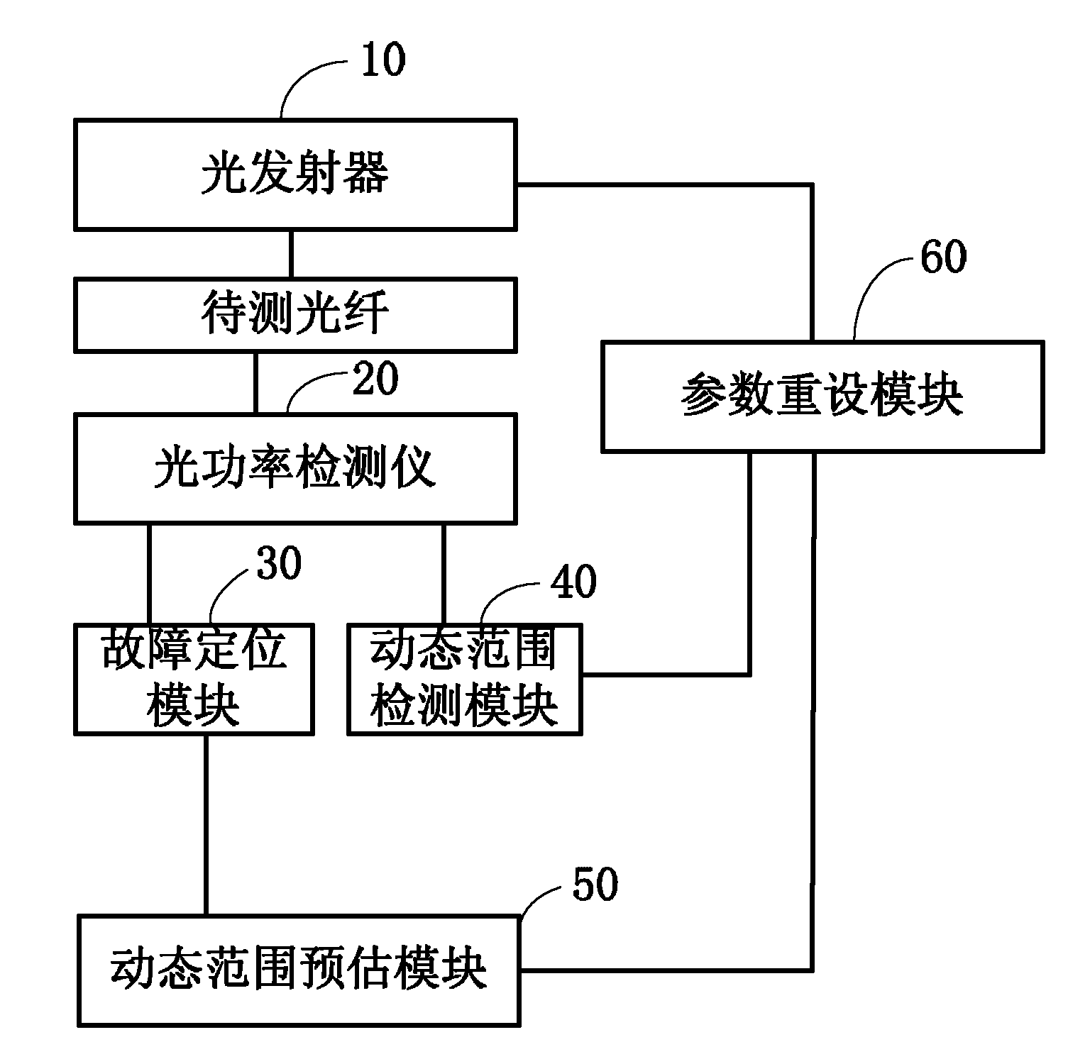
[0028] Please refer to figure 1 A preferred embodiment of the optical fiber fault location system of the present invention includes an optical transmitter 10 , an optical power detector 20 , a fault location module 30 , a dynamic range detection module 40 , a dynamic range estimation module 50 and a parameter reset module 60 .

[0029] The optical transmitter 10 is used to transmit the first test light to the optical fiber to be tested to be trans...


PUM


Abstract

The invention relates to an optical fiber failure positioning system and method. The optical fiber failure positioning method comprises the following steps of: sending out testing light at preset pulse width and pulse time interval to be transmitted in an optical fiber to be detected; detecting the power loss of the testing light; initially determining the failure position of the optical fiber according to the power loss of the testing light; determining a dynamic range of the testing light according to the power loss of the testing light; estimating a dynamic range of secondary testing light required when the optical fiber to be detected is monitored for the second time according to the initially determined failure position of the optical fiber; re-determining the pulse width and the pulse time interval according to the relationship among the dynamic range of the testing light, the pulse width and the pulse time interval; sending out secondary testing light at the re-determined pulse width and the pulse time interval to be transmitted in the optical fiber to be detected; detecting the power loss of the secondary testing light; and positioning the secondary failure for the optical fiber to be detected according to the power loss of the secondary testing light. By adopting the system and the method, the accuracy of optical fiber failure positioning can be improved.

Description

technical field [0001] The present application relates to a fault location system, in particular to a fiber optic fault location system and method. Background technique [0002] In recent years, optical fiber communication technology has been vigorously developed. Optical fiber communication not only realizes long-distance transmission of signals, but also has stable performance of transmitted signals. In the optical fiber monitoring technology, a light source is placed at the far end of the client to emit test light. After the test light propagates in the optical fiber of the client under test, it is received by an OTDR (Optical Time Domain Reflectometer, Optical Time Domain Reflectometer). Medium propagation will be attenuated due to scattering. OTDR can analyze whether the optical fiber under test is abnormal by analyzing the power attenuation of the test light. A solution is proposed for fault location, but the positioning accuracy is not enough, and maintenance personn...

Claims


Application Information

Patent Timeline
IPC IPC(8): H04B10/08H04B10/077H04B10/079
Inventor 付勇王伟
Owner 北京锐锋钝石科技有限公司
Why Eureka
Try Eureka