
Sea chest cooler comprising an integrated antifouling system

A sea valve box and cooler technology, applied in the direction of damage protection, indirect heat exchangers, heat exchanger types, etc., can solve problems such as susceptibility to interference, complicated technical investment, etc., and achieve the effect of saving energy costs and saving purchase costs

Active Publication Date: 2011-06-08
冈特·赫费尔
View PDF5 Cites 14 Cited by
  • Summary
  • Abstract
  • Description
  • Claims
  • Application Information

AI Technical Summary

Problems solved by technology

[0006] The disadvantage of the above-mentioned invention is that it requires changes to the ship's structure, for example due to the need to install a ram for closing the discharge opening of the sea chest
[0009] The disadvantage of the above arrangement is that the inlet funnel / funnel arrangement and the outlet funnel have to be mechanically connected to each other in different cavities of the cooler cover, whereby the inlet funnel can be positioned above the inlet and the outlet funnel in the same heat transfer cell above the outlet so that the inlet and outlet funnels can be disconnected from the cooling circuit and protected from fouling in a separate heating circuit
The technological input for mechanically coupling the two funnels to each other is very complex and susceptible to interference

Method used


Image

  • Sea chest cooler comprising an integrated antifouling system
  • Sea chest cooler comprising an integrated antifouling system
  • Sea chest cooler comprising an integrated antifouling system

Examples


Embodiment Construction

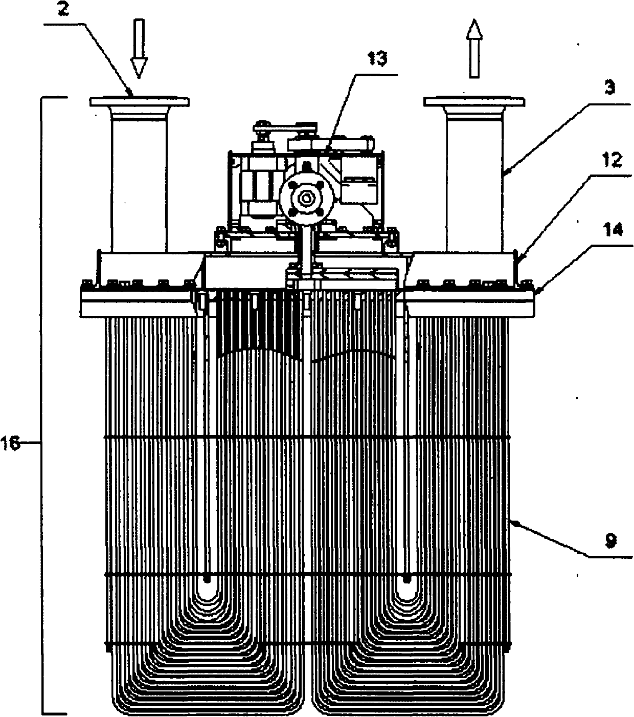
[0024] Figure 1a A sea chest cooler 16 is shown with its main components such as the tube bundle 9, cover 12 and integrated TAS unit 13. The engine cooling water enters the space formed by the cover 12 and the tube plate 14 of the sea chest cooler 16 via the inlet connection 2 .

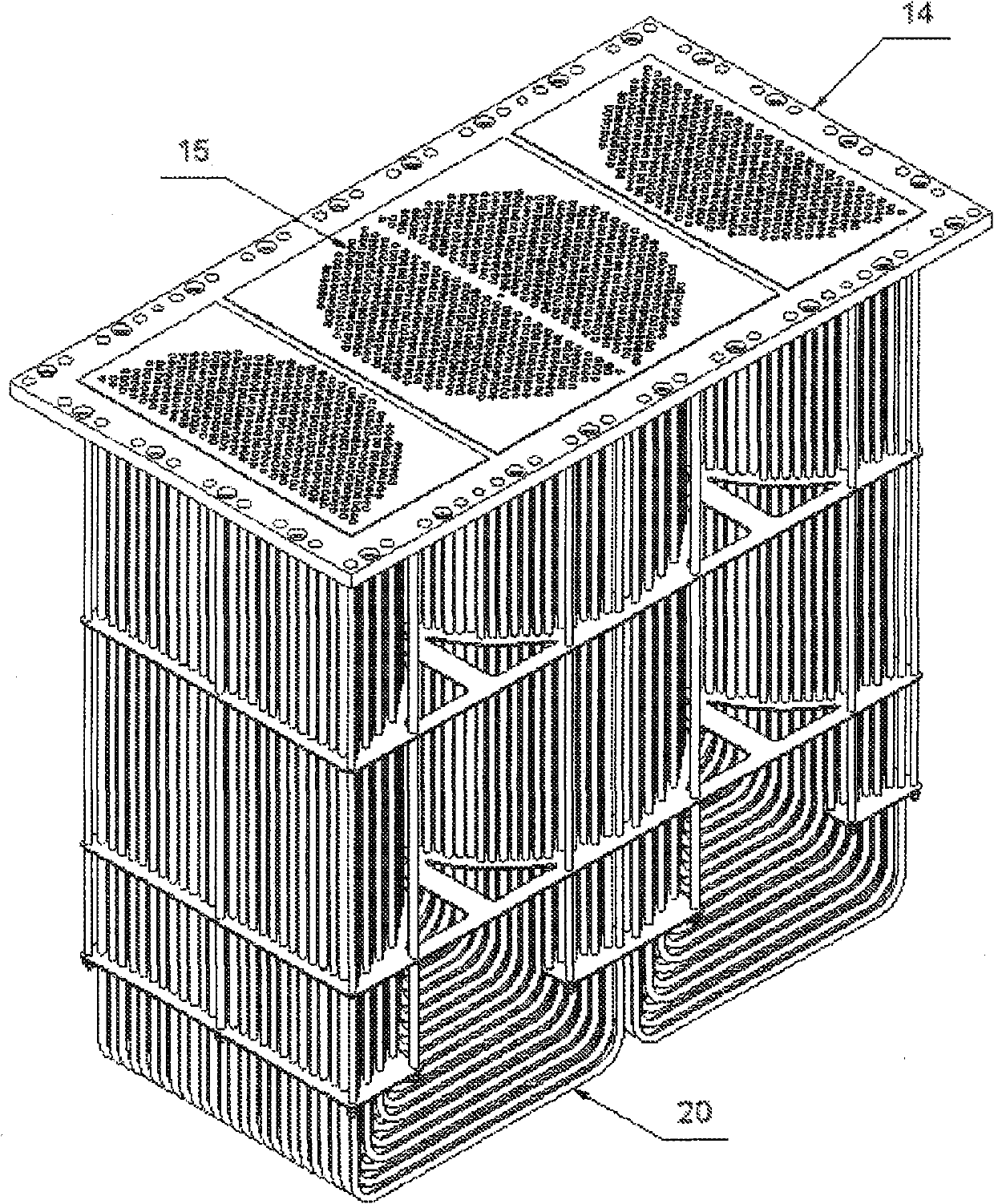
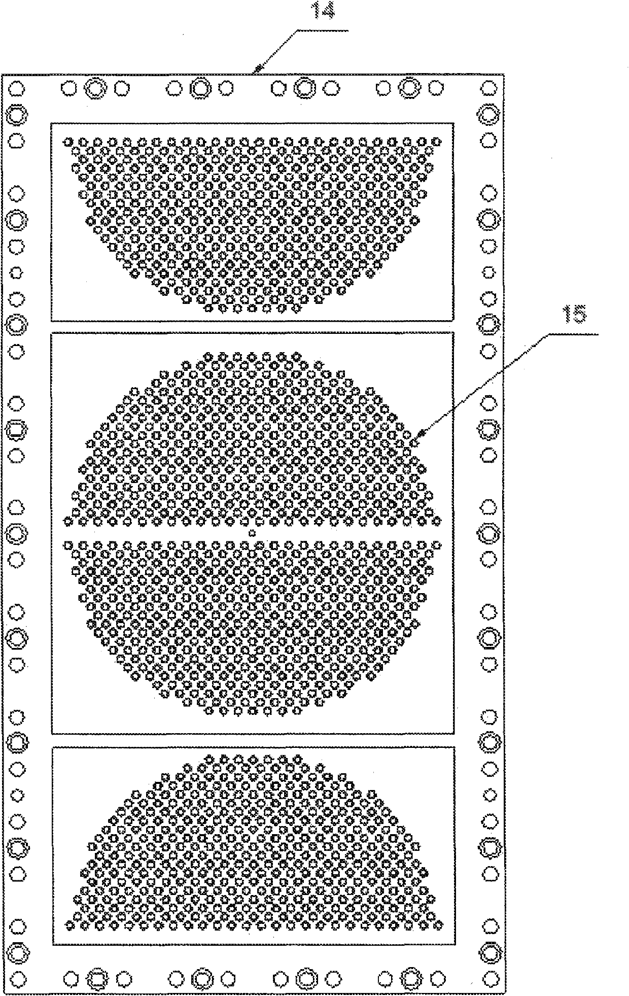
[0025] Figure 1b and Figure 1c Shown is a structural embodiment of the tube plate 14, which has a circular arrangement of U-shaped tubes and nozzle chambers 21 (see Figure 1a ) in the middle tube sheet area, on which TAS nozzle 1 (see Figure 1a ) through the TAS device 13 (see Figure 1a ) work purposefully in order to protect the heat exchange tube 20 (see Figure 1a ) from defacement.

[0026] Such as figure 2 As shown, the heated water flows to a small number of heat exchange tubes 20 of the tube bundle 9 through the TAS water inlet 8 with the shut-off valve 10 and the rotary guide 6 leading into the TAS nozzle 1 in order to heat these heat exchange tubes. The rotating guide device 6 seal...


PUM


Abstract

The invention relates to a sea chest cooler on ships and offshore platforms, comprising an integrated antifouling system for killing barnacles, mussels, and other fouling organisms by means of an overheating process that can be regularly repeated. The aim of the invention is to design a sea chest cooler in such a way that a simple device can automatically protect the sea chest cooler (16) against microorganism fouling both in the actual cooling mode and during a standstill by continuously overheating a defined number of heat exchanger tubes (20) without interrupting the cooling process, if possible using waste heat from the cooling water. Said aim is achieved by arranging the heat exchanger tubes in a circular manner in special sections of the sea chest cooler (16) such that hot water is supplied to individual circular segments of the tube bundle during or outside the cooling process by means of a mechanical device. Said thermal antifouling system (TAS) device (13) comprises a TAS nozzle (1) which rotates in angular steps and separates heat exchanger tubes (20) of the sea chest cooler (16) from the cooling process. The invention has the advantage that the cooler design is adapted to the simultaneous cooling and antifouling function and that the sea chest cooler comprising the integrated TAS device can be protected against fouling by using the waste heat from the cooling water without interrupting the cooling process.

Description

technical field [0001] The invention relates to a sea chest cooler (Seekastenküler) on ships and offshore platforms, in which barnacles, flapbranchs and other pollutants are killed by periodically (regularly) repeatable overheating via an integrated antifouling system damaging organisms. Background technique [0002] Fouling on ships, ship components and in piping systems and components thereof is increasing dramatically, especially due to increased pollution of water bodies. Various measures have been taken internationally to try to reduce or avoid such fouling. [0003] A method and a device are described in DE-PS 19921433 C1, the task of which is to develop efficient, environmentally friendly methods and devices for ships, offshore platforms, etc., for occasional or continuous contact with seawater in sea chests Inhibit and avoid fouling on piping, filters, heat exchangers, fittings, pumps, sea chest coolers. [0004] The method is characterized in that: the seawater i...

Claims


Application Information

Patent Timeline
IPC IPC(8): B63B59/00
CPCF28D1/022F28F19/00B63B2013/005F28G13/005B63B59/00F28D7/06B63B59/04
Inventor 冈特 赫费尔
Owner 冈特·赫费尔
Learn More