
Shift arrangement for a motor vehicle variable speed gearbox

A technology for motor vehicle transmissions and shift shafts, which is applied to mechanical equipment, components with teeth, transmission control, etc., and can solve problems such as precise manufacturing of complex processing steps and assembly steps

Inactive Publication Date: 2014-01-01
SCHAEFFLER TECH AG & CO KG
View PDF8 Cites 0 Cited by
  • Summary
  • Abstract
  • Description
  • Claims
  • Application Information

AI Technical Summary

Problems solved by technology

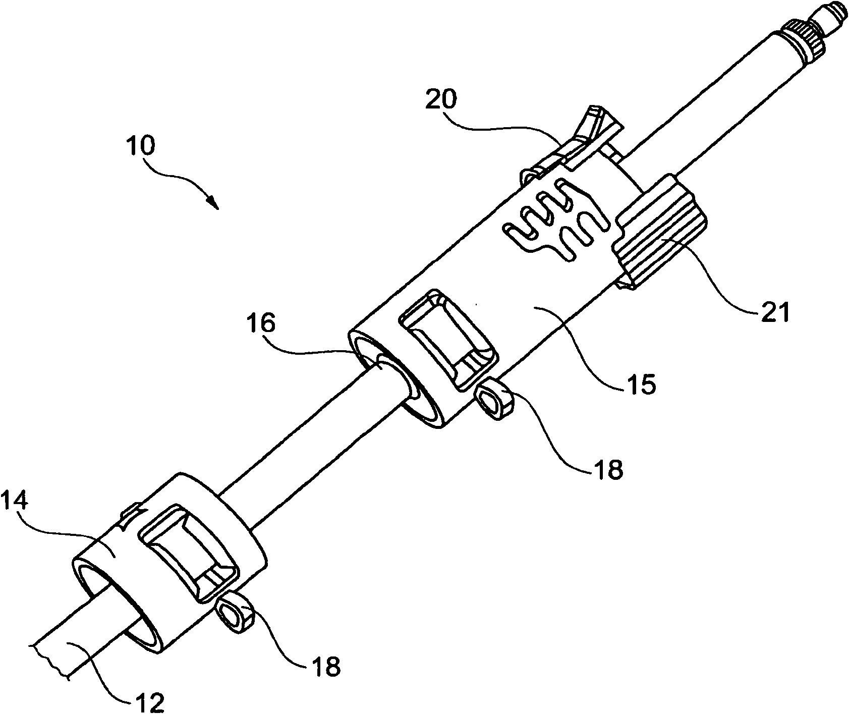
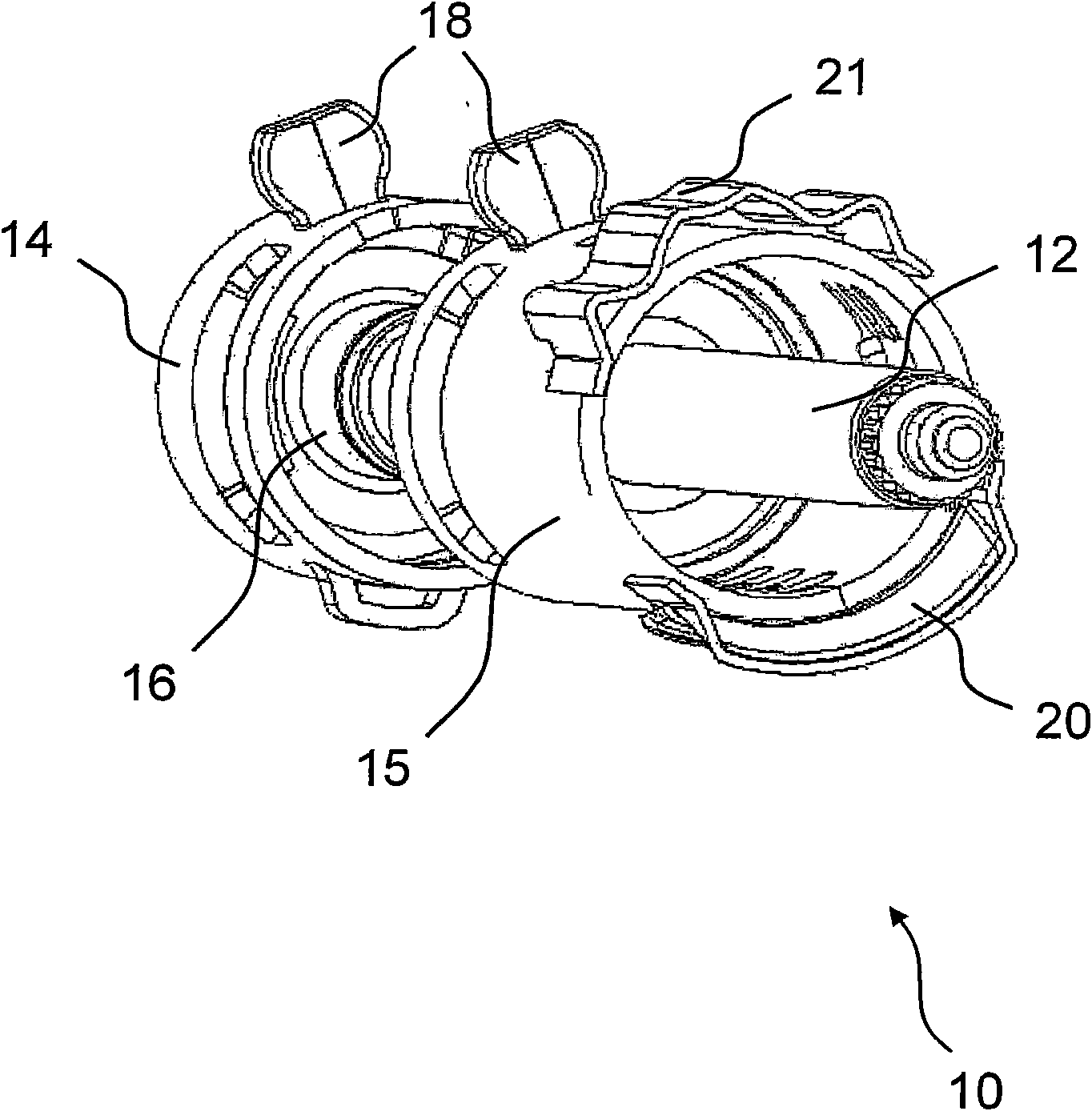
Furthermore, the sheet metal shells 14, 15 serving as locking cylinders are welded to the central shaft 12, just as the latches 20, 21 are welded to the sheet metal shell 15, which requires precise manufacturing with tight tolerances and is relatively complex processing steps and assembly steps

Method used


Image

  • Shift arrangement for a motor vehicle variable speed gearbox
  • Shift arrangement for a motor vehicle variable speed gearbox
  • Shift arrangement for a motor vehicle variable speed gearbox

Examples


Embodiment Construction

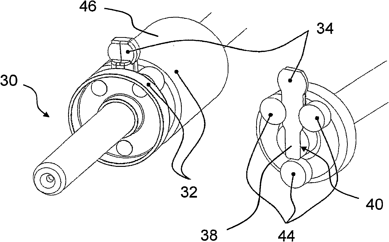
[0028] Figure 2 to Figure 4 The schematic illustration of FIG. 1 shows a first variant of a shift shaft 30 for a motor vehicle transmission according to the invention. The shift shaft 30 is mounted in the housing in a pivotable and longitudinally displaceable manner. The shift shaft 30 has a lock cylinder 32 on its outer circumference and an operating element in the form of a shift finger 34 and a detent piece 36, which is arranged on the lock cylinder 32, and is used to cooperate with the corresponding shift elements of the transmission. effect. The selector finger 34 has a pin 38 which engages in the transverse direction in a corresponding recess 40 of the selector shaft 30 and is thus positively connected to the selector shaft 30 . The locking cylinder 32 is formed by a plurality of discs 42 each having a central bore, so that the locking cylinder 32 can be pushed over the cylindrical shaft 30 without play. After assembly of the discs 42 and the shift fingers 34 arrange...


PUM


Abstract

The present invention relates to a shift arrangement of a motor vehicle variable speed gearbox, comprising a selector shaft (30), which is supported pivotally and longitudinally displaceably in a housing, and which at the outer circumference thereof comprises at least one locking cylinder (32) and at least one shift finger (34) for interaction with shifting elements of the gearbox, said shift finger protruding radially from the locking cylinder (32). According to the invention, the at least one shift finger (34) is positively and non-rotatably connected to the selector shaft (30) and fixed between mutually adjoining individual parts of the locking cylinder (32).

Description

technical field [0001] The invention relates to a shifting system for a motor vehicle transmission having the features of the preamble of claim 1 . Background technique [0002] In known motor vehicle transmissions with manual or automatic controls, the different gear stages are selected and shifted by means of suitable shifting systems. Such a shifting system can in particular be designed as a shifting shaft or as a so-called control drum system. Such a shifting system is articulated to a manual shift lever or to a suitable actuator and is preferably guided in a rolling bearing within the housing. In order to preselect a gear, the selector shaft can be pushed and twisted to change gears. A transmission element is arranged on the selector shaft, which is used to position or transmit the shifting movement to the component, which is connected downstream of the selector shaft. This could be, for example, a shift pawl which is held in connection with a sliding sleeve of the t...

Claims


Application Information

Patent Timeline
Patent Type & Authority Patents(China)
IPC IPC(8): F16H63/20
CPCF16H2061/243F16H63/30F16H2063/3076F16H2061/242F16H2063/3083
Inventor 托马斯·克莱伯
Owner SCHAEFFLER TECH AG & CO KG
Learn More