
Freeze-drying device

A technology of drying device and ejector, applied in drying gas arrangement, drying solid materials, drying and other directions, can solve problems such as hindering self-freezing and difference in particle size of raw material particles.

Inactive Publication Date: 2011-06-08
ULVAC INC
View PDF5 Cites 3 Cited by
  • Summary
  • Abstract
  • Description
  • Claims
  • Application Information

AI Technical Summary

Problems solved by technology

The deviation of the height position at which the self-freezing is completed will hinder the smooth self-freezing of each liquid column, which in turn will cause differences in the particle diameters of the raw material particles

Method used


Image

  • Freeze-drying device
  • Freeze-drying device
  • Freeze-drying device

Examples


Embodiment Construction

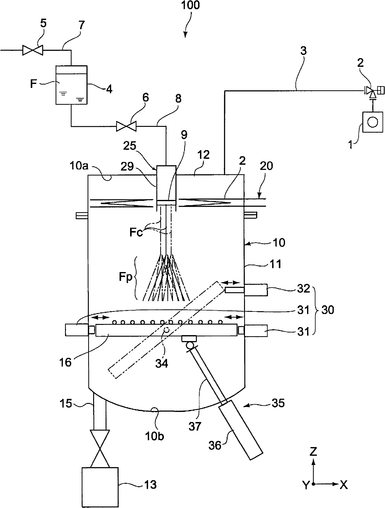
[0015] A freeze-drying apparatus in one embodiment of the present invention has a vacuum chamber and an ejector. Wherein, the vacuum chamber may be subjected to decompression treatment.

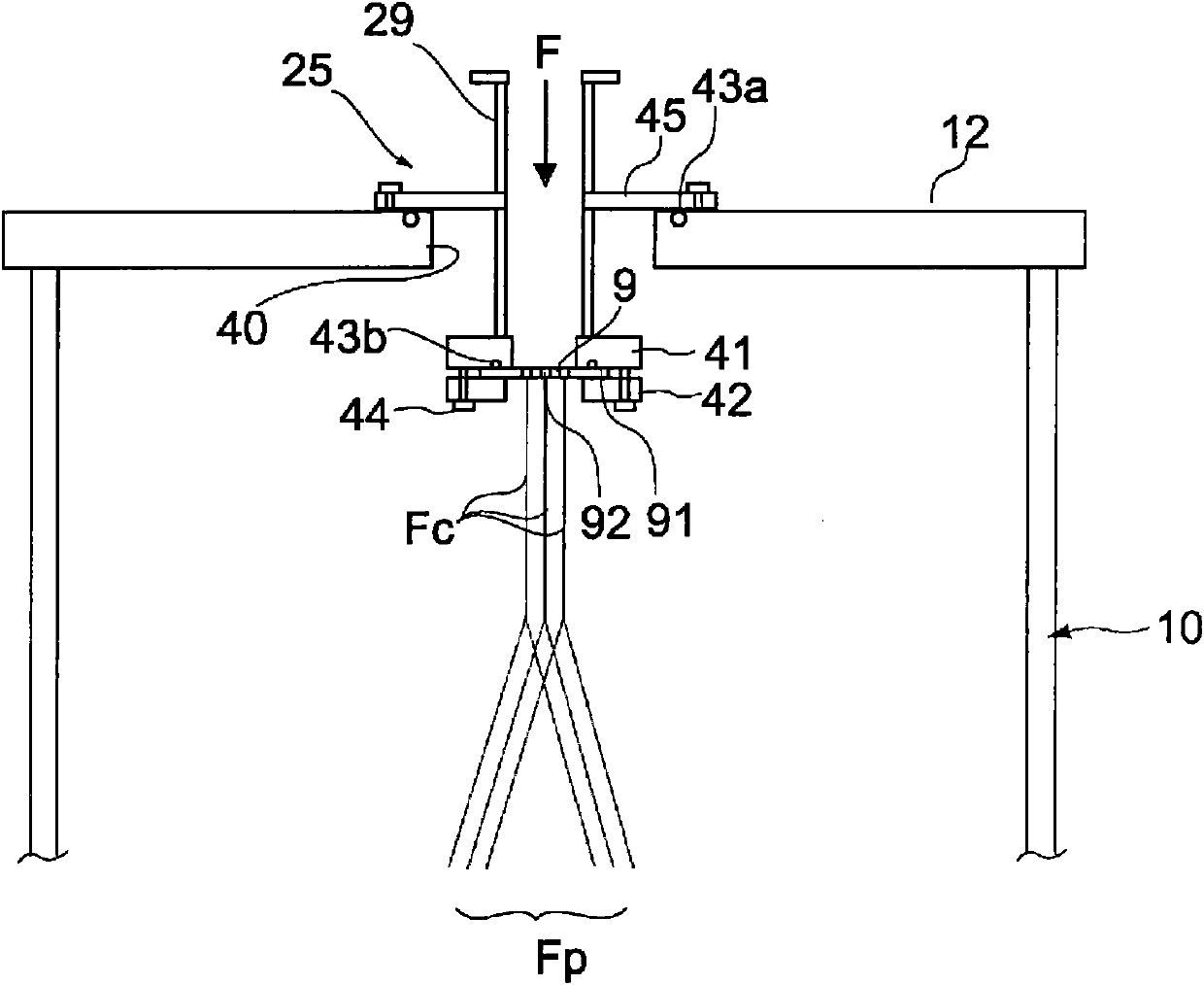
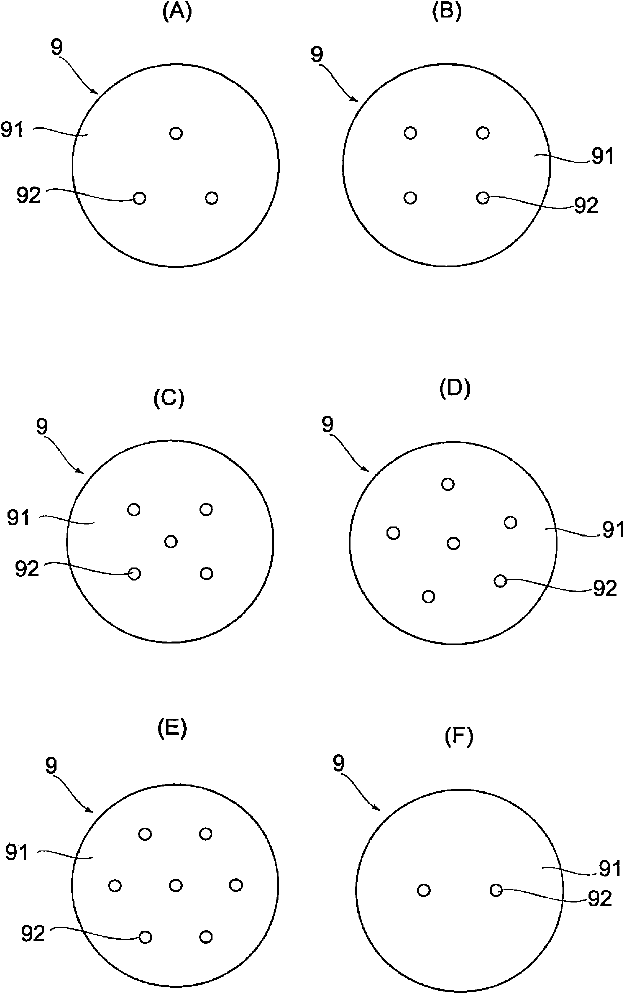
[0016] The injector has a tubular member and a nozzle. Wherein, the tubular component is arranged in the vacuum chamber. The nozzle is arranged on the tubular part, and the nozzle has a plurality of spray holes facing the interior of the tubular part. The raw material liquid introduced into the tubular member is injected into the vacuum chamber from the nozzle of the injector.

[0017] In the freeze-drying device, the raw material liquid sprayed from each injection hole of the nozzle will form a separate liquid column in the vacuum chamber, and then freeze at a predetermined height to form raw material particles, and finally the raw material particles will be in the form of mist dispersion. At this time, since each spray hole is formed to face the inside of the tubular member, the raw mat...


PUM


Abstract

Provided is a freeze-drying device that can improve processing capacity while avoiding variability in grain size. A freeze-drying device (100) pertaining to an embodiment of the invention is equipped with a freezing bath (10) constituting a vacuum chamber and an injector (25). The injector (25) has a pipe member (29) provided inside the vacuum chamber and a nozzle (9) with multiple injection holes (92) that faces the inner side of the pipe member (29). The injector (25) injects a raw material fluid (F), that is supplied to the pipe member (29), into the vacuum chamber through the nozzle (9). Because the respective injection holes (92) are formed so as to face the inner side of the pipe member (29), the raw material fluid (F) is injected through the respective injection holes (92) at the same injection pressure. As a result, the processing capacity can be improved while avoiding variability in grain size.

Description

technical field [0001] The invention relates to a jetting freeze-drying device, the principle of which is to spray raw material liquid into a vacuum environment to make it freeze automatically. Background technique [0002] In the spray type freeze-drying device, the raw material liquid of the raw materials such as medicine, food, cosmetics, etc. is sprayed in the vacuum chamber, and the raw material liquid is prepared by dissolving or dispersing the raw material with a solvent or a dispersant. In the spraying process, the heat of vaporization of the solvent is used to absorb heat from the raw material, so that the raw material can not only be frozen but also dried into particulate form, and the particulate material is collected by the collector installed at the lower part of the vacuum chamber. In addition, in order to promote this drying action, the raw material is heat-treated with a resistance heating heater installed on the collector. [0003] For example, the followin...

Claims


Application Information

Patent Timeline
IPC IPC(8): A23L3/44F26B17/10F26B5/06
CPCF26B5/065A23L3/44F26B21/004F26B5/06F26B17/10
Inventor 伊藤薰树中村久三加藤丈夫伊藤胜彦木下贵夫
Owner ULVAC INC
Learn More