Data transmission device, data reception device, method for transmitting data, method for receiving data, and method for controlling audio-visual environment

A technology of a data sending device and a data receiving device, which is applied in the direction of TV, selective content distribution, pulse modulation TV signal transmission, etc., and can solve the problem that it is difficult for users to judge whether to turn on the lighting

Inactive Publication Date: 2011-06-08
SHARP KK
View PDF7 Cites 11 Cited by
  • Summary
  • Abstract
  • Description
  • Claims
  • Application Information

AI Technical Summary

Problems solved by technology

[0005] However, in the existing method, if the specifications of the user's lighting device do not strictly support the lighting conditions (for example, the brightnes

Method used


Image

  • Data transmission device, data reception device, method for transmitting data, method for receiving data, and method for controlling audio-visual environment
  • Data transmission device, data reception device, method for transmitting data, method for receiving data, and method for controlling audio-visual environment
  • Data transmission device, data reception device, method for transmitting data, method for receiving data, and method for controlling audio-visual environment

Examples


Embodiment approach 1

[0091] (data sending device)

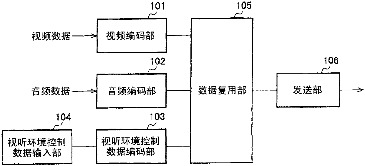
[0092] First, a data transmission device will be described. figure 1 It is a functional block diagram showing a schematic configuration of a data transmission device according to an embodiment of the present invention.

[0093] The data transmission device is composed of a video encoding unit 101 , an audio encoding unit 102 , an audio-visual environment control data encoding unit 103 , an audio-visual environment control data input unit 104 , a data multiplexing unit 105 and a transmission unit 106 .

[0094] The input video data is compression-coded by the video coding unit 101 and output to the data multiplexing unit 105 . Various compression methods such as ISO / IEC13818-2 (MPEG-2Video), ISO / IEC14496-2 (MPEG-4Visual), ISO / IEC14496-10 (MPEG-4AVC) can be used for video encoding.

[0095] Similarly, the input audio data is compression-encoded by the audio encoding unit 102 and output to the data multiplexing unit 105 . Various compression meth...

Embodiment approach 2

[0152] (data sending device)

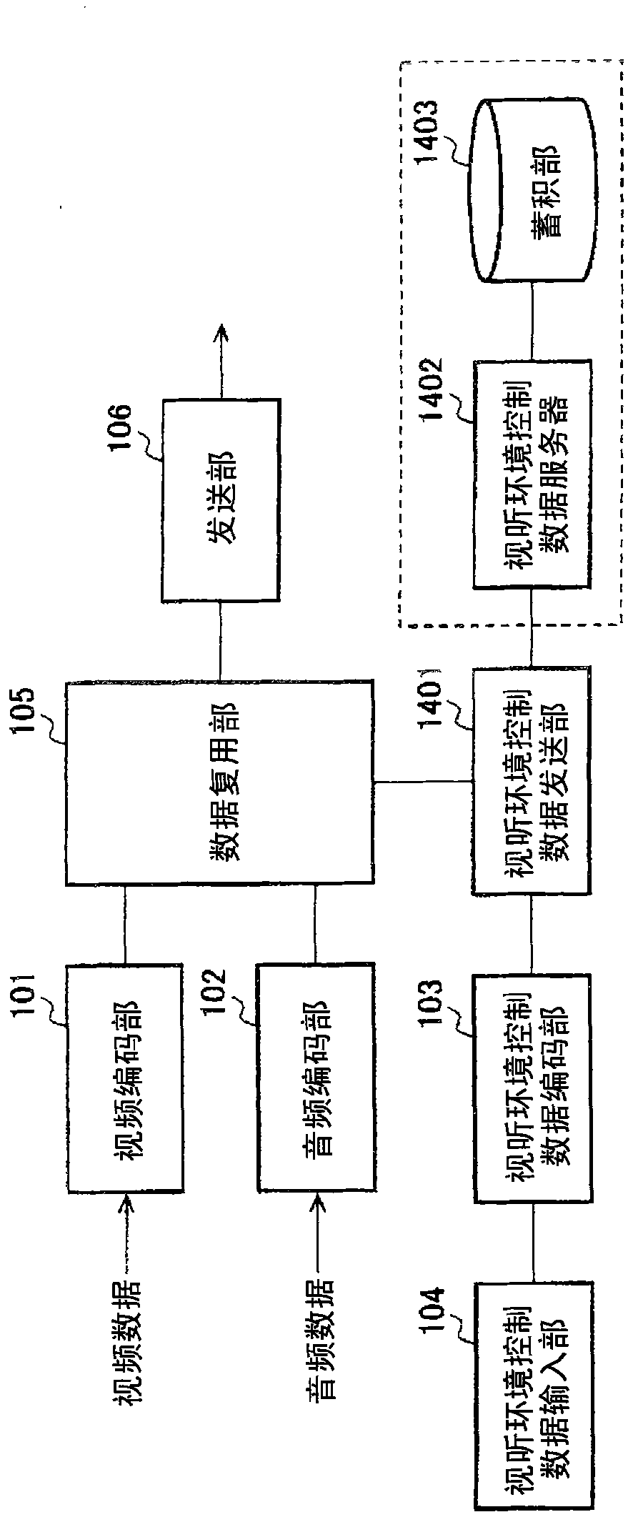
[0153] The schematic configuration of the data transmission device in this embodiment is the same as that in Embodiment 1. figure 1 , figure 2 and image 3 same. In this embodiment, the operation of the audio-visual environment control data input unit 104 is different from that in the first embodiment.

[0154] Figure 13 (A) is an example of the case where audio-visual environment control data including lighting effects preferred by the creator are described in XML, Figure 13 (B) is a schematic representation of the tree structure Figure 13 (A) Diagram of XML description.

[0155] exist Figure 13 In this, unlike the first embodiment, not only the control data (ControlData), but also the device control data (DeviceControlDescription) and lighting control data (DeviceControlData: light1, light2) of the entire content can be described over multiple layers. Note that the description of preference is not essential, and when it is assumed ...

Embodiment approach 3

[0167] In Embodiments 1 and 2, an example of the preference applied to the lighting control unit was shown, and the second preference applied to the entire audio-visual environment control data was also described. That is, when a certain lighting control condition is not satisfied, a disallowed category flag can also be described, and the disallowed category flag selection is to disallow all control of the lighting in the content (the control of the lighting that meets the condition is also not allowed) Also, only the control of the lighting that does not meet the conditions is not permitted (the control of the lighting that meets the conditions is permitted).

[0168] In addition, the above-mentioned non-permission category identifier can be sent and received together with each control data in the content, or can be sent and received before the actual control data.

[0169] Figure 16 (A) is an example in the case where audio-visual environment control data for lighting effe...


PUM


Abstract

Provided are a data transmission device, a data reception device, a method for transmitting data, a method for receiving data, and a method for controlling audio-visual environment that carry out the control of peripheral devices in consistence with contents producer's intention, thereby realizing the listening/viewing of the contents with a realistic sensation. The data transmission device is comprised of a video coding unit (101), an audio coding unit (102), an audio-visual environment control data coding unit (103), an audio-visual environment control data input unit (104), a data multiplexing unit (105) and a transmission unit (106). A control designation value for the peripheral devices and producer's preference information indicative of an acceptable error range for the control designation value are inputted from the audio-visual environment control data input unit (104), as audio-visual environment control data for one or more peripheral devices in an audio-visual environmental space where video data and/or audio data are reproduced, and the control designation value and the preference information are transmitted together with the video data and/or the audio data.

Description

technical field [0001] The present invention relates to a data transmission device, a data reception device, a data transmission method, a data reception method, and an audio-visual environment control for transmitting and receiving data for operating various peripheral devices in conjunction with video / audio content in order to realize content viewing with a strong sense of presence method. Background technique [0002] In recent years, a method of realizing content viewing with a strong sense of presence has been proposed by operating various peripheral devices such as lighting, fans, and air conditioners in the viewing space in conjunction with video / audio content. For example, Patent Documents 1 and 2 disclose a lighting control method that achieves a strong sense of presence by controlling the lighting of an audio-visual environment in conjunction with an image displayed on an image display device. [0003] Patent Document 1: Japanese Patent Laid-Open No. 2000-173783 ...

Claims


Application Information

Patent Timeline
IPC IPC(8): H04N7/24H04N7/14
CPCH04N21/435H04N21/42202H04N21/4131H04N21/235H04N21/8543H04N21/8186H04N21/43615H04N7/173
Inventor 德毛靖昭荻泽义昭岩波琢也伊藤典男渡部秀一长谷川伸也吉井隆司
Owner SHARP KK
Why Eureka
Try Eureka