Brush

A technology of brushes and brush handles, which is applied in the field of cleaning tools, can solve the problems of inconvenient storage and storage, impact on health, poor durability of loofah blocks, etc., and achieve the effect of convenient storage and storage

Inactive Publication Date: 2011-06-15
姚志刚
View PDF2 Cites 5 Cited by
  • Summary
  • Abstract
  • Description
  • Claims
  • Application Information

AI Technical Summary

Problems solved by technology

[0002] In the Chinese patent literature, there are disclosed brushes that are particularly suitable for cleaning cookware such as pots and pans. As the utility model patent authorization announcement number CN2400057Y, the scrubbing brush recommended by the loofah block and the handle is composed of a loofah block and a handle, and the loofah block is fixed on the handle with rivets. The head, the brush with this structure has an ideal effect for removing oil stains, but there are the following deficiencies: first, it is difficult to remove the stubborn dirt attached to the surface of the pot, because the loofah block is a compliant body; second, it is easy to cause Secondary pollution, because greasy sticks to the loofah block, it is easy to pollute the loofah block, and if it is not cleaned, it is easy to breed bacteria; the third is that the loofah block has poor durability and needs to be replaced frequently
Another example is that the brush provided by the authorized announcement number CN2629645Y is composed of a body and a brush body formed of a handle and a fixed pin. Therefore, it is easy to shed debris during use (in the process of brushing), and if it is neglected to remove, it will easily affect health; second, because the brush body is a very fluffy ball group, the comb-shaped fixing pin is easy to penetrate through the brush during use. body, so that the fixed pin is in direct hard contact with the pot body and damages the pot body (scratches the surface of the pot body); the third is poor sanitation, the inside of the brush body is often in a wet state, and it is difficult to dry, so it is easy to breed bacteria and cause two pollutions ; Four, because the brush body and the main body are separated in the non-use state, it is not convenient for collection and storage

Method used


Image

  • Brush
  • Brush

Examples


Embodiment Construction

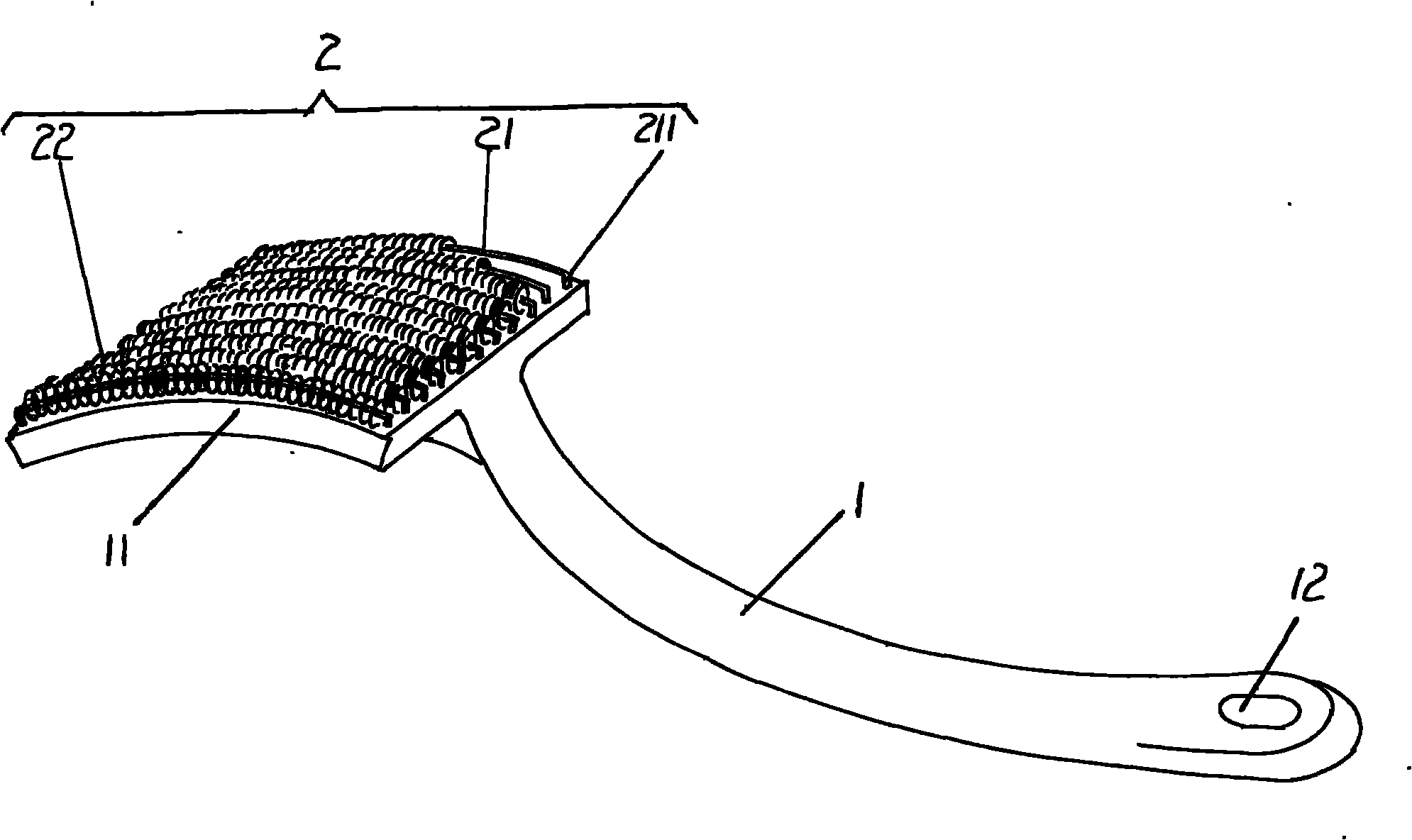
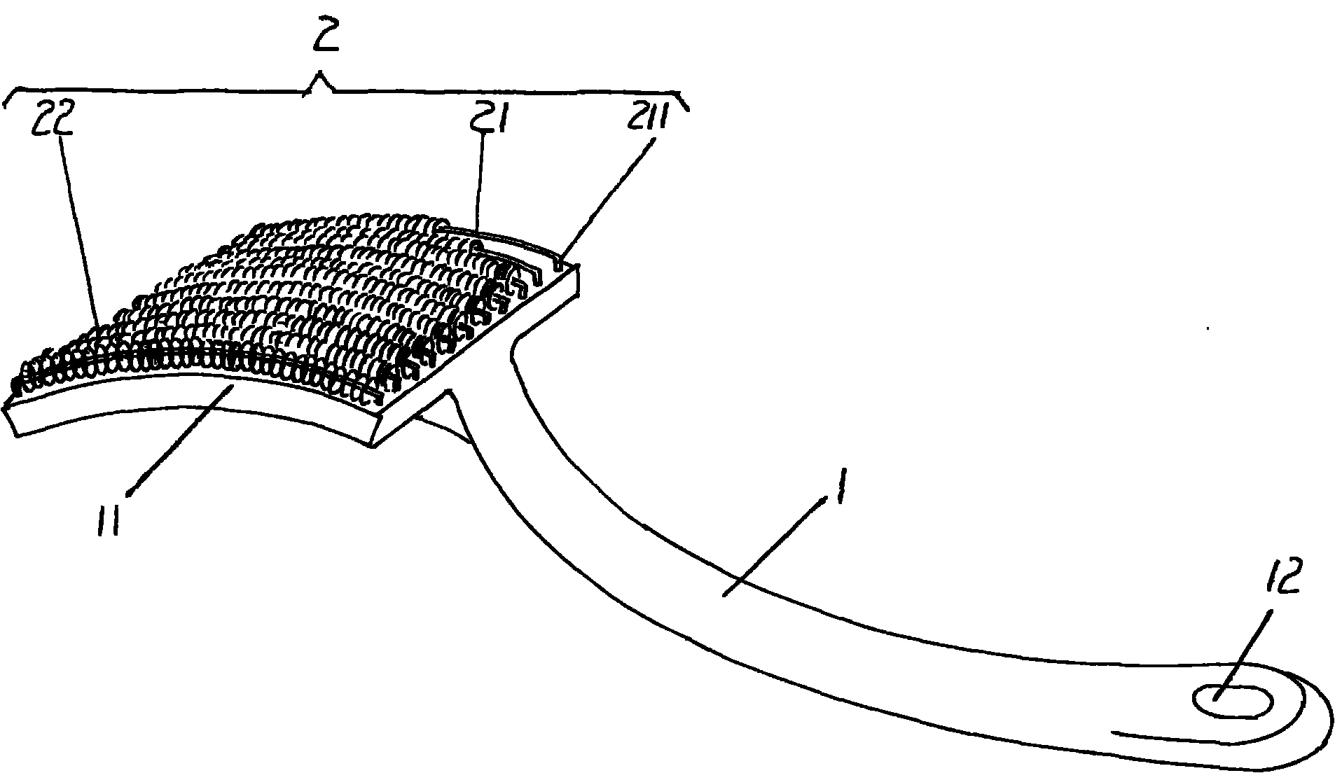
[0007] Please see the accompanying drawings, one end of the provided brush handle 1, that is, the right end of the position shown in the figure, has a hanging hole 12, and the other end of the brush handle 1, that is, the left end of the figure, has a brush body positioning plate 11, and the brush body is positioned The plate 11 is made integrally with the brush handle 1 . The brush body 2 is set on the surface of one side of the brush body positioning plate 11, the brush body 2 includes a group of spring ring positioning bars 21 and a group of spring rings 22, and the quantity of one group of spring rings 22 is the same as that of a group of spring coil positioning bars 21. The numbers are equal, specifically: a group of spring ring positioning strips 21 are fixed to the brush body positioning plate 11 through the positioning feet 211 at both ends in the same way, and the adjacent spring coil positioning strips 21 are kept parallel to each other, and each spring coil A helica...


PUM


Abstract

The invention discloses a brush, which belongs to the technical field of cleaning appliances. The brush comprises a brush handle and a brush body arranged on the brush handle, wherein a brush body positioning plate is formed at one end of the brush handle; the brush body comprises spring ring positioning strips and spring rings; the number of the spring rings is equal to that of the spring ring positioning strips; the spring ring positioning strips are fixed on the brush body positioning plate in parallel at intervals; and one spring ring is sleeved on each spring ring positioning strip. Through the technical scheme, scales stubbornly adhered on a pot can be effectively cleaned by the spring rings and the surface of the pot cannot be damaged; because the spring rings have spaces, the dryness of the pot is easy to keep and bacteria growth is avoided; the brush handle and the brush body are integrated, so the brush is easy to store.

Description

technical field [0001] The invention belongs to the technical field of cleaning appliances, and in particular relates to a brush. Background technique [0002] In the Chinese patent literature, there are disclosed brushes that are particularly suitable for cleaning cookware such as pots and pans. As the utility model patent authorization announcement number CN2400057Y, the scrubbing brush recommended by the loofah block and the handle is composed of a loofah block and a handle, and the loofah block is fixed on the handle with rivets. The head, the brush with this structure has an ideal effect for removing oil stains, but there are the following deficiencies: first, it is difficult to remove the stubborn dirt attached to the surface of the pot, because the loofah block is a compliant body; second, it is easy to cause Secondary pollution, because greasy sticks on the loofah block, it is easy to pollute the loofah block, and if it is neglected to clean, it is easy to breed bact...

Claims


Application Information

Patent Timeline
Patent Type & Authority Applications(China)
IPC IPC(8): A47L17/04
Inventor 姚志刚
Owner 姚志刚
Why Eureka
Try Eureka