Catheter intervention device with conveying resistance feedback function

A catheter intervention and function technology, applied in catheters, medical science, surgery, etc., can solve the problems of interference, the intervention device is not compact, the structure is not compact enough without the feedback function of conveying resistance, etc., to enhance safety and avoid radiation damage. Effect

Inactive Publication Date: 2011-06-15
HARBIN INST OF TECH
View PDF3 Cites 19 Cited by
  • Summary
  • Abstract
  • Description
  • Claims
  • Application Information

AI Technical Summary

Problems solved by technology

[0003] The purpose of the present invention is to provide a catheter interventional device with delivery resistance feedback function to solve the problem that the existing catheter interventional device is not compact enough, has no delivery resistance feedback function, and interventional surgeons must operate on the surgica

Method used


Image

  • Catheter intervention device with conveying resistance feedback function
  • Catheter intervention device with conveying resistance feedback function
  • Catheter intervention device with conveying resistance feedback function

Examples


specific Embodiment approach 1

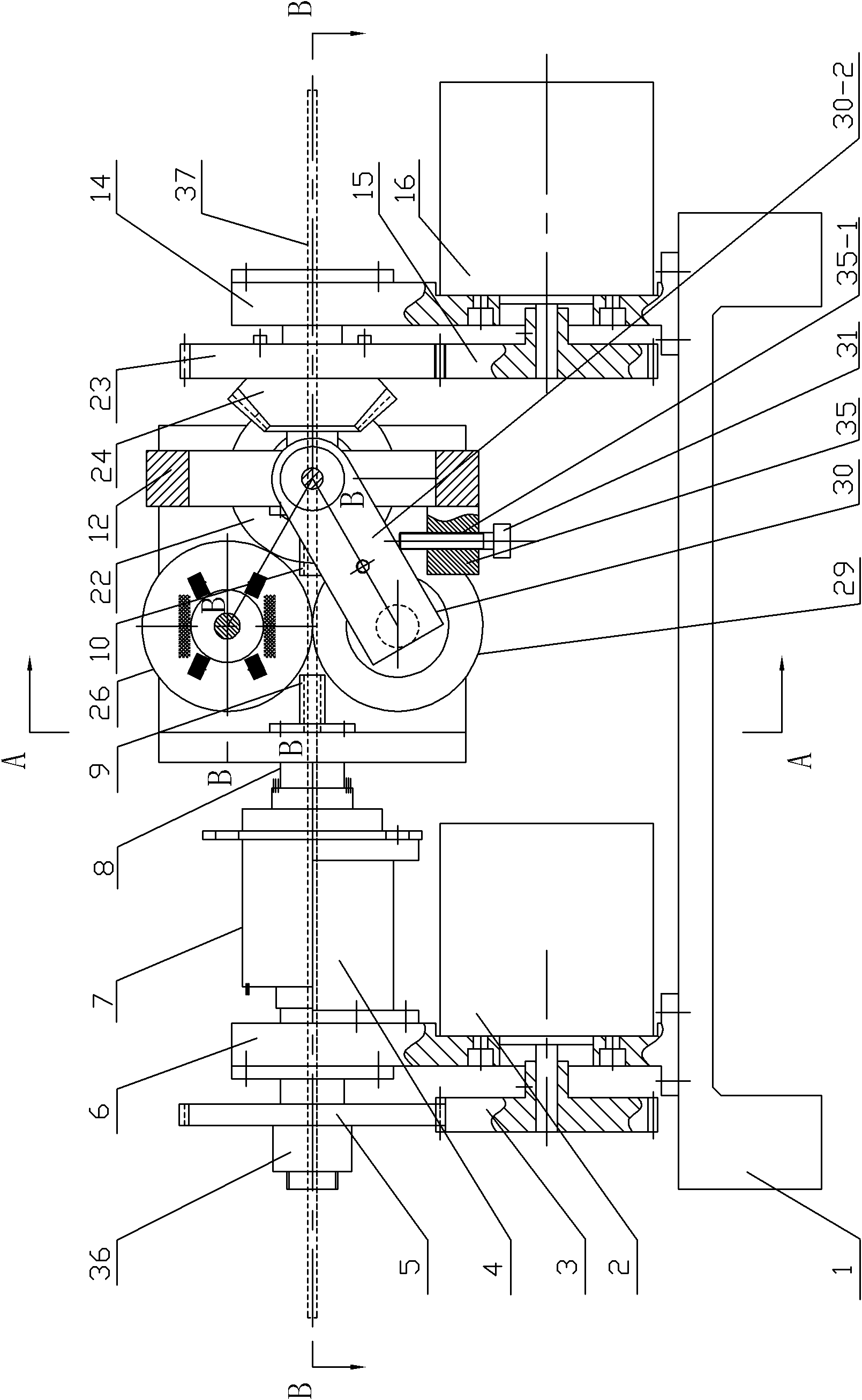
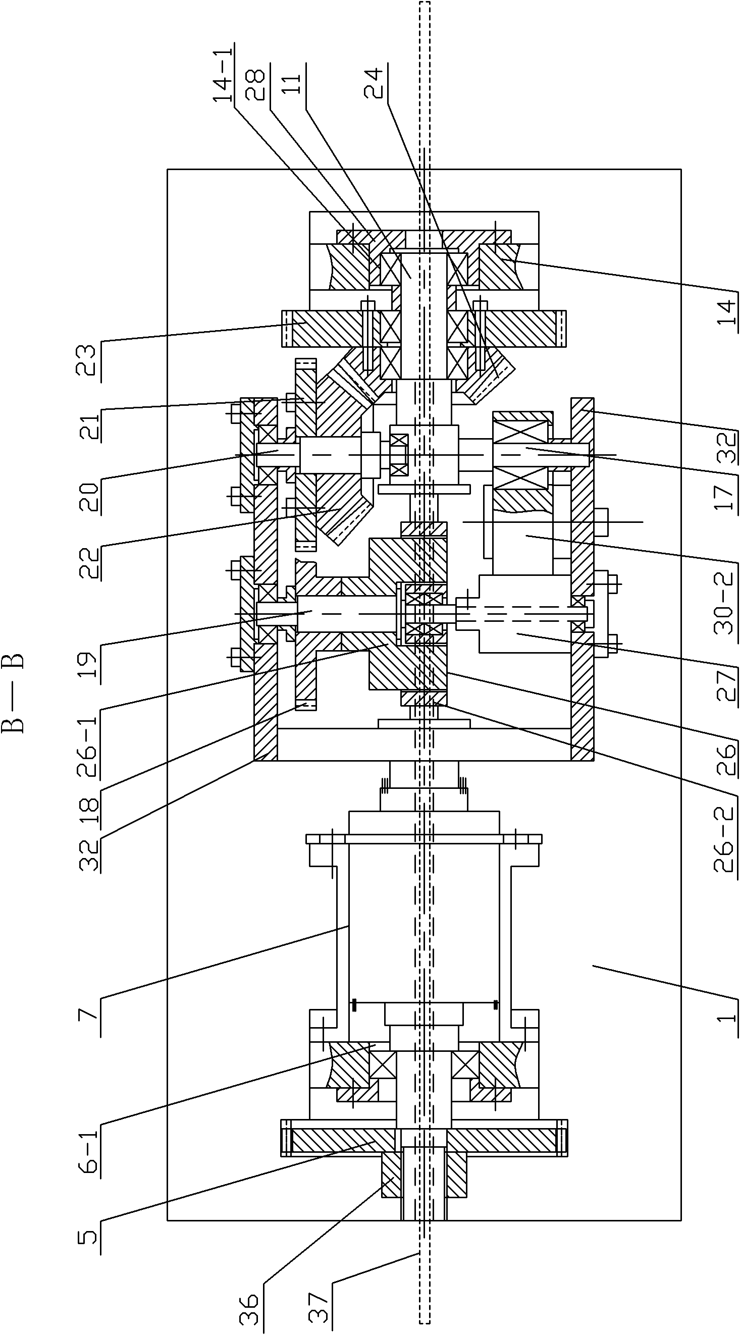
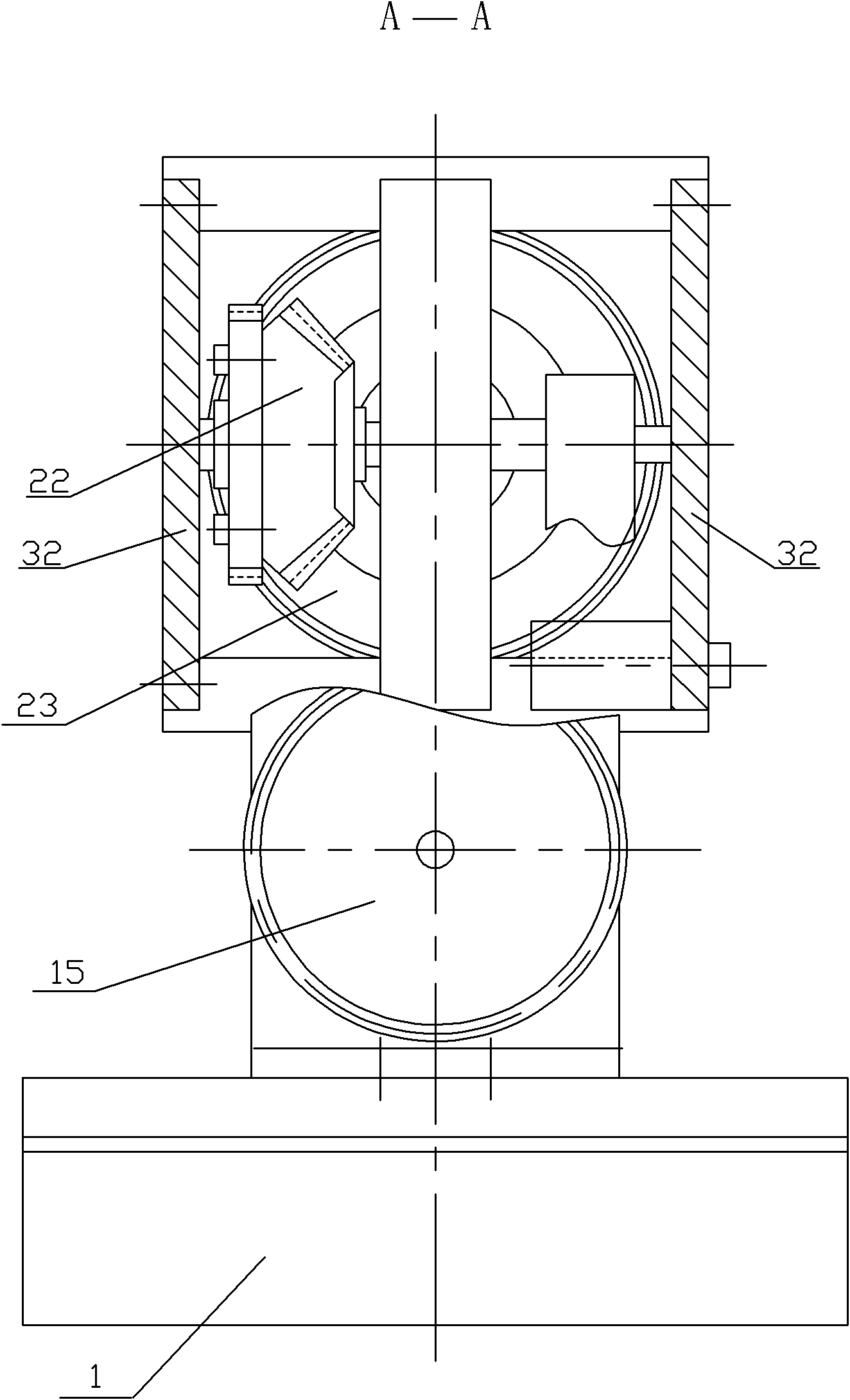
[0007] Specific implementation mode one: combine Figure 1 to Figure 13Describe this embodiment, the catheter intervention device in this embodiment includes a base 1, a left motor 2, a right motor 16, and a left driving gear 3; the catheter intervention device also includes a conductive slip ring support 4, a left slave Moving gear 5, left support frame 6, first conductive slip ring 7, rotating bracket 8, left catheter guide sleeve 9, right catheter guide sleeve 10, first connecting shaft 11, I-shaped support beam 12, right Support frame 14, primary driving gear 15, second connecting shaft 17, tertiary driven gear 18, active friction wheel shaft 19, bevel gear shaft 20, tertiary driving gear 21, secondary driven bevel gear 22, primary driven gear Driven gear 23, secondary driving bevel gear 24, driving friction wheel 26, second conductive slip ring 27, right end cover 28, driven friction wheel 29, L-shaped driven friction wheel rotating support arm 30, driven friction wheel l...

specific Embodiment approach 2

[0010] Specific implementation mode two: combination Figure 10 with Figure 11 Note that the rotating bracket 8 in this embodiment is composed of a rotating shaft 8-1 and a rotating plate 8-2; one end of the rotating shaft 8-1 is fixedly connected to the center of one end surface of the rotating plate 8-2, so that The structure is simple and easy to manufacture. Others are the same as in the first embodiment.

specific Embodiment approach 3

[0011] Specific implementation mode three: combination figure 2 with Figure 11 Explain that in this embodiment, the outer wall of the other end of the rotating shaft 8-1 is processed with an external thread, and the rotating shaft 8-1 is processed with a shoulder 8-1-1 near the external thread, and the left driven gear 5 passes through and The gear lock nut 36 to which the rotary shaft 8-1 is threaded and the end face of the shoulder 8-1-1 of the rotary shaft 8-1 are positioned axially. With such arrangement, the structure is simple and the positioning effect is good. Others are the same as in the second embodiment.


PUM


Abstract

The invention relates to a catheter intervention device with the conveying resistance feedback function, belonging to a catheter intervention device, and aiming at solving the problems that the existing catheter intervention device is not compact in structure, does not have the conveying resistance feedback function and is operated at the surgical site by doctors getting involved the surgery. Output shafts of a left and a right motors are fixedly sheathed with a left side driving gear and a first-stage driving gear; the left side driving gear is meshed with a left side driven gear; the first-stage driving gear is meshed with a first-stage driven gear; a second-stage driving bevel gear is fixedly connected with the first-stage driven gear; the second-stage driving bevel gear is meshed with a second-stage driven bevel gear; a third-stage driving gear is fixedly connected with the second-stage driven bevel gear; the third-stage driving gear is meshed with a third-stage driven gear; a driving friction inner wheel is fixedly provided with a touch force sensor; the driving friction inner wheel is connected with a driving friction outer wheel by the touch force sensor; a signal output end of the touch force sensor is connected with a signal input end of an amplification circuit board; and an amplifying signal output end of the amplification circuit board is connected with a signal input end of an inner ring of a second electric conduction sliding ring. The catheter intervention device is used for continuously conveying a catheter and feedback of the force.

Description

technical field [0001] The invention relates to a catheter intervention device, in particular to a catheter intervention device with a delivery resistance feedback function used in intravascular minimally invasive interventional operations. Background technique [0002] In the traditional minimally invasive vascular interventional surgery, the intubation operation is performed manually by the doctor at the surgical site. There are many disadvantages in this operation method: (1) The environment of the surgical site is poor. The doctor not only suffers from radiation damage, but also has to bear heavy pressure Lead clothing; (2), the operation is not stable enough, and the accuracy is not easy to guarantee. Therefore, it is necessary to develop a dedicated catheter intervention device to replace the doctor to complete various operations at the operation site, so that the doctor can perform master-slave operations in the operating room separated from the operating room. Since...

Claims


Application Information

Patent Timeline
IPC IPC(8): A61M25/082A61B17/00
Inventor 付宜利梁兆光刘浩高安柱李凯王树国
Owner HARBIN INST OF TECH
Why Eureka
Try Eureka