X-ray flaw detector verification platform and measurement method

A radiographic flaw detection and X-ray technology, which is applied in the field of X-ray flaw detector verification platform, can solve the problems of excessive radiation leakage, radiation beam deviation, poor irradiation sensitivity, etc.

Pending Publication Date: 2020-05-15
HENAN PROVINCE INST OF METROLOGY
View PDF7 Cites 4 Cited by
  • Summary
  • Abstract
  • Description
  • Claims
  • Application Information

AI Technical Summary

Problems solved by technology

[0005] In view of the above situation, in order to overcome the defects of the prior art, the present invention provides a verification platform for X-ray flaw detectors, which effectivel

Method used


Image

  • X-ray flaw detector verification platform and measurement method
  • X-ray flaw detector verification platform and measurement method
  • X-ray flaw detector verification platform and measurement method

Examples


Embodiment 1

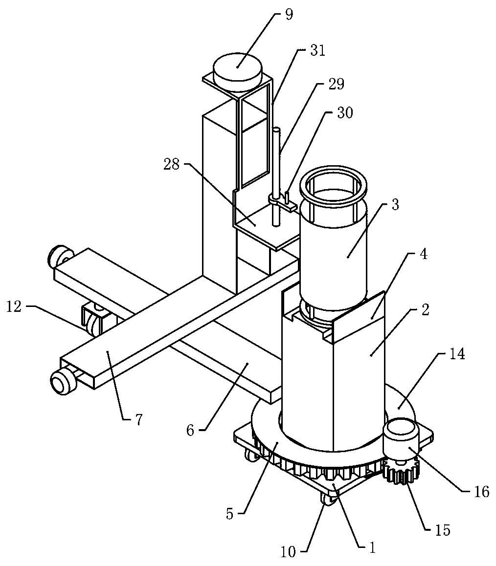
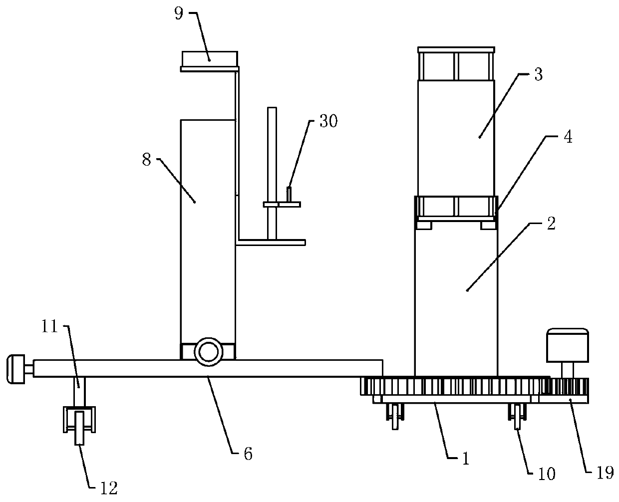
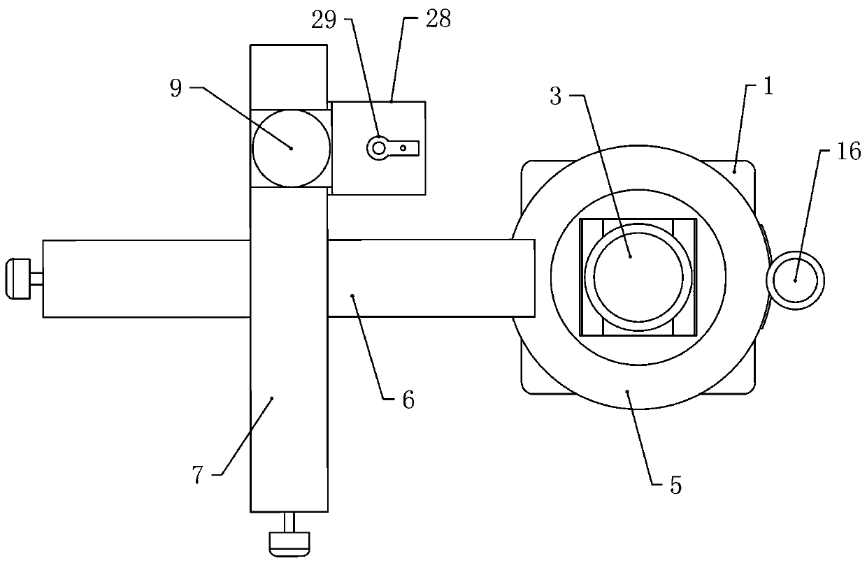
[0062] Embodiment 1, a verification platform for an X-ray flaw detector, including a central stand 1, the central stand 1 is a square, with chamfers at the four corners, a placing platform 2 is fixed on the central stand 1, and the placing platform 2 is vertical The cube of X-ray flaw detection machine 3 is fixedly installed above the placement platform 2, and the window of X-ray flaw detection machine 3 is equipped with a shielding cover 4, and 5 rotating platforms are installed on the central stand 1, and the rotating platform 5 can rotate. The rotating platform 5 is circular, and the center is hollow. The rotating platform 5 is set on the outside of the placing platform 2. When the rotating platform 5 rotates, the placing platform 2 does not rotate. The upper surface of the rotating platform 5 is equipped with a radial moving platform 6, following The rotating platform 5 rotates together, and the horizontal moving platform 7 is installed on the radial moving platform 6, and ...

Embodiment 2

[0063] Embodiment 2, on the basis of Embodiment 1, four first universal wheels 10 are installed below the central stand 1 to facilitate the movement of the central stand 1. The first universal wheels 10 have a brake function. The outer end of the radially movable platform 6 is connected to the second universal wheel 12 through the fixed rod 11. The second universal wheel 12 has a braking function, and the second universal wheel 12 can rotate around the placement platform 2.

Embodiment 3

[0064] Embodiment 3, on the basis of Embodiment 1, the rotating platform 5 includes a large gear 13, a gear cover 14 is installed on the outside of the large gear 13, and a pinion 15 is meshed on the side of the large gear 13, and the pinion 15 is connected to a second gear through a rotating shaft. A stepping motor 16, the bottom of the bull gear 13 rotates and is installed on the central stand 1, the first stepping motor 16 starts to drive the pinion 15 to rotate, the pinion 15 meshes with the bull gear 13 to rotate, and the bull gear 13 drives the gear cover 14 Rotating, the gear cover 14 drives the radially moving platform 6 to rotate around the placement platform 2 .


PUM


Abstract

The invention relates to an X-ray flaw detector verification platform and a measurement method, and effectively solves the problems that an existing flaw detector is insufficient in penetrating power,radiation beams deviate, the irradiation sensitivity is poor and the leaked rays exceed the standard. The X-ray flaw detector verification platform comprises a center rack, a placing platform is fixed on the center rack; an X-ray flaw detector is fixed on the placing platform; a shielding cover is arranged outside the X-ray flaw detector; a rotating platform which can rotate and is arranged on the outer side of the placing platform in a sleeving manner is mounted on the center rack; a radial moving platform is mounted on the rotating platform; a transverse moving platform is installed on theradial moving platform, a lifting platform is installed on the transverse moving platform, a dosimeter is installed on the lifting platform. The platform can not only measure the radiation dose and the radiation beam size in a high-precision mode, but also visually and accurately draw the state of the radiation beam so as to improve the industrial flaw detection accuracy.

Description

technical field [0001] The invention relates to the technical field of ionizing radiation measurement, in particular to an X-ray flaw detector verification platform and a measurement method. Background technique [0002] X-ray flaw detector refers to an X-ray generating device used for non-destructive testing of industrial product components. It is a device that generates X-rays by bombarding the anode target with high-speed electrons, shines through the inspected part, and obtains an image of the internal structure of the part on a film or other imaging device, and judges whether the inspected part is defective. X-ray flaw detectors have been widely used in ships, boilers, pressure, containers, chemicals, construction, special equipment and other fields. [0003] At present, there are thousands of flaw detector manufacturers in my country, and there are a considerable number of imported equipment. During the inspection, it is found that there are generally quality problems...

Claims


Application Information

Patent Timeline
IPC IPC(8): G01N23/04
CPCG01N23/04
Inventor 王双玲王攀峰李胜春袁晶晶龙成章高申星刘辉李静唐盟毛哲高颖周云森
Owner HENAN PROVINCE INST OF METROLOGY
Why Eureka
Try Eureka