
Method and equipment for processing mineral by jointly using gravity, centrifugal force and vibration force

A kind of mineral processing equipment and centrifugal force technology, applied in chemical instruments and methods, solid separation, wet separation, etc., can solve the problems that the mineral processing effect needs to be improved, the separation efficiency is low, and the structure is complex.

Inactive Publication Date: 2012-10-31
XUZHOU INST OF ARCHITECTURAL TECH
View PDF1 Cites 0 Cited by
  • Summary
  • Abstract
  • Description
  • Claims
  • Application Information

AI Technical Summary

Problems solved by technology

But no matter how it is improved, there are still many weaknesses in traditional gravity concentrators that use inclined plane flow for separation.
Single vibratory concentrator and centrifugal concentrator have relatively low separation efficiency
The Chinese patent "Vertical Centrifugal Concentrator" with application number 88209020.8, although it utilizes the combination of gravity and centrifugal force, can work continuously and partially solves the above problems, but it is not combined with vibration force, and the beneficiation effect still needs to be improved, and more complicated structure

Method used


Image

  • Method and equipment for processing mineral by jointly using gravity, centrifugal force and vibration force
  • Method and equipment for processing mineral by jointly using gravity, centrifugal force and vibration force
  • Method and equipment for processing mineral by jointly using gravity, centrifugal force and vibration force

Examples


Embodiment Construction

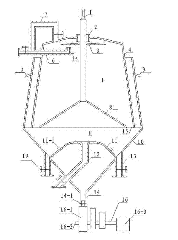
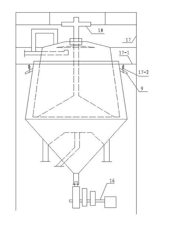
[0095] Below in conjunction with embodiment the present invention is further described. Such as figure 1 with figure 2 The shown mineral processing equipment utilizes gravity, centrifugal force and vibration force at the same time, including vertically arranged upper cone 4 and lower cone 10. The top of the cone 10 is open; the upper middle of the upper cone 4 has a pulp inlet 2, and the upper cone 4 is provided with a rotating shaft 1 along the central axis of the upper cone, and the rotating shaft 1 passes through the pulp inlet 2 and external power The device is connected; the upper part of the upper cone 4 is provided with an upper tailings pipe 6, the upper cone 4 is fixed on the bracket 17, the lower cone 10 is movably connected to the bracket 17, and the lower part of the upper cone 4 is set In the upper part of the lower cone 10, there is a gap between the outer wall of the upper cone 4 and the inner wall of the lower cone 10 to ensure that the lower cone 10 does no...


PUM


Abstract

The invention disclose a method and equipment for processing mineral by jointly using gravity, centrifugal force and vibration force, belonging to the technical field of industrial mineral separation. The equipment comprises an upper conic cylinder and a lower conic cylinder which are perpendicular to each other; a rotating shaft is arranged in the upper conic cylinder along the center axis of the upper conic cylinder; the upper conic cylinder is fixed on a support; the lower conic cylinder is movably connected with the support; the lower part of the upper conic cylinder is sleeved in the upper part of the lower conic cylinder; the upper end of the rotating shaft can be rotationally fixed on the support; a stream guide disc is fixed on the middle part of the rotating shaft; a conic rotating disc is fixed on the lower end of the rotating shaft; a gap is left between the edge of the conic rotating disc and the inner wall of the upper conic cylinder to form a circular seam; the upper part of the upper conic cylinder is provided with an air intake pipe; the inlet of an upper tailing pipe is provided with a slurry measuring sensor; a vibration table is fixed in the lower conic cylinder; a material measuring sensor is arranged on the vibration table; a concentrate pipe is connected to the wall of the lower conic cylinder; a vibration joint is fixed on the lower end of the lower conic cylinder; and the vibration joint is connected with a vibration mechanism.

Description

technical field [0001] The invention belongs to the technical field of industrial mineral separation, and in particular relates to a mineral processing equipment and a mineral processing method. Background technique [0002] With the rapid development of science and technology and economy and the reduction of rich ore resources, the growing industrial demand cannot be met, so it is forced to mine and sort out the lean ore resources (such as iron, gold and other minerals) that have large reserves and are difficult to select. This requires high-efficiency beneficiation equipment to obtain high-quality mineral resources from low-content mineral resources. Beneficiation is carried out according to the difference in specific gravity between useful minerals and gangue minerals, which is called gravity separation. Because this method plays a very important role in expanding mineral resources and comprehensive utilization; in particular, it is convenient to operate, low in producti...

Claims


Application Information

Patent Timeline
Patent Type & Authority Patents(China)
IPC IPC(8): B03B7/00
Inventor 于殿宝
Owner XUZHOU INST OF ARCHITECTURAL TECH
Learn More