

Crystal-block bonding rod slicing process
A technology of ingot and sticking rod, applied in the field of solar cell wafer slicing, can solve the problems of scrapping the whole knife, scrapping the whole knife, and affecting the slicing efficiency, so as to avoid wire breakage and improve the yield and production capacity.
Active Publication Date: 2011-06-15
TRINA SOLAR CO LTD
View PDF4 Cites 11 Cited by
- Summary
- Abstract
- Description
- Claims
- Application Information
AI Technical Summary
Problems solved by technology
However, in the cutting process, it is unavoidable that there will be inclined planes, line marks, and knife marks at both ends of the crystal block.
During the slicing process of the crystal block, the slopes, line marks and knife marks at both ends of the crystal block are likely to bend the cutting steel wire, "climbing lame phenomenon", and even cause the steel wire to break, so that a large number of Hidden cracks, thick and thin slices, line marks, missing corners and fragments, even lead to the scrapping of the entire crystal block, seriously affecting the efficiency of slicing
At present, there is no solution in the industry at home and abroad to solve the ratio of hidden cracks, thick slices, line marks, missing corners and fragments at both ends of the crystal block during the slicing process caused by the bevels at both ends of the crystal block, line marks, and knife marks. Reports of positive and effective methods of staying high or even scrapping the whole knife
Method used
View moreImage
Smart ImageViewing Examples

Examples
Embodiment 1
[0014] Embodiment 1 and Embodiment 2 can adopt MB-264, MB-271 and HCT various model slicing machines, loading capacity is 800mm / 1000mm, use normal slicing process and battery process, adopt crystal block slicing sticky stick of the present invention, The slicing qualification rate and quality of silicon wafers, as well as the yield and efficiency of the battery side have all been improved according to statistics.
Login to View More PUM
 Abstract
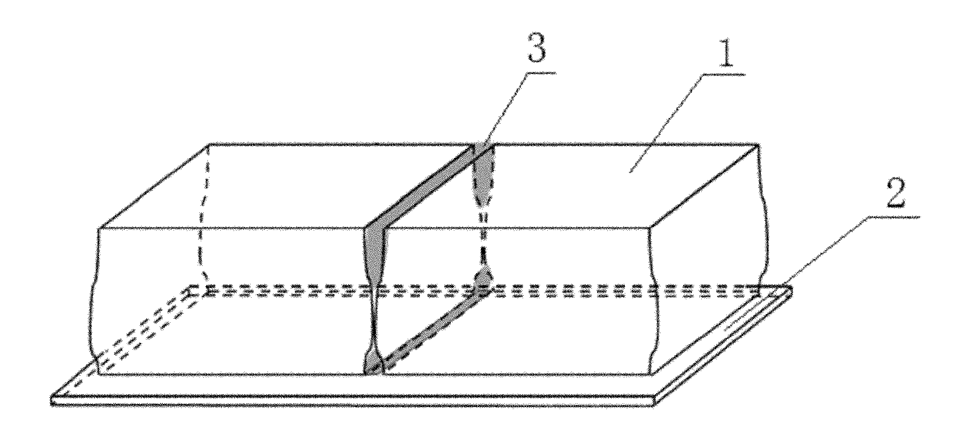
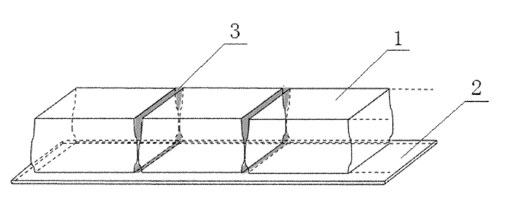
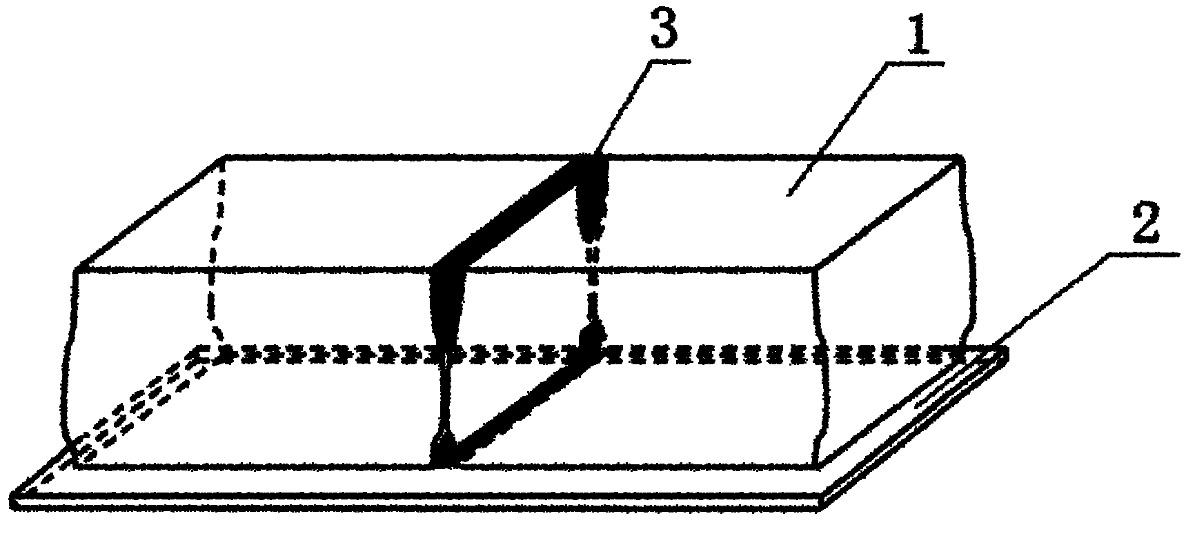
The invention relates to a crystal-block bonding rod slicing process. The process comprises the following steps: adhering more than two crystal blocks on the same glass plate to form a crystal-block bonding rod, wherein unqualified semi-finished product crystal blocks which are not cut are arranged on two ends of the crystal block; unqualified parts of the two adjacent crystal blocks are closely connected, and the connecting gap of the unqualified parts of the two adjacent crystal blocks is filled with glue; and the crystal block is sliced by a slicing machine after the glue is solidified. The crystal-block sliced bonding rod is a seamless bonding rod, and the unqualified parts on two ends of the crystal block are not required to be cut before the crystal block is sliced so as to save a cutting process and eliminate bevel, line trace and cut trace caused by cutting two ends of the crystal block; therefore, the problem of high proportion of hidden splinters, thick and thin slices, line traced slices, notch slices and fragment on two ends of the crystal block in a slicing process is fundamentally solved, occurrence of broken line is avoided, yield and capacity of silicon slices is greatly improved, and quality guarantee is provided for the silicon slices on a battery end.
Description
technical field [0001] The invention relates to the technical field of solar cell crystal block slicing, in particular to a crystal block sticky rod slicing process. Background technique [0002] At present, when slicing solar cell ingots, usually before the ingots enter the slicing machine for slicing, structural steel wires, diamond wires or band saws are used to cut off the unqualified parts at both ends of the ingots, such as impurity layers or low carrier counts. Life layer, etc., and then fix the crystal block on the crystal support and enter the slicer table for slicing. However, it is unavoidable that inclined planes, line marks, and knife marks will be produced at both ends of the crystal block during the cutting process. During the slicing process of the crystal block, the slopes, line marks and knife marks at both ends of the crystal block are likely to bend the cutting steel wire, "climbing lame phenomenon", and even cause the steel wire to break, so that a larg...
Claims
Login to View More Application Information
Patent Timeline
 Patent Type & AuthorityApplications(China)
IPC IPC(8): B28D5/00
Inventor贺洁
OwnerTRINA SOLAR CO LTD