Choke feeding screw conveyor
A screw conveyor and material feeding technology, which is applied in packaging and other directions, can solve the problems of easy blockage and large gas consumption, and achieve the effects of preventing overflow, high conveying speed and compact structure
Inactive Publication Date: 2011-06-15
刘振亮
View PDF4 Cites 5 Cited by
- Summary
- Abstract
- Description
- Claims
- Application Information
AI Technical Summary
Problems solved by technology
When feeding the closed tank, in order to prevent the gas in the tank from overflowing, gas-blocking feeding is required. At present, pneumatic conveying is mostly used to realize gas-blocking feeding. Pneumatic conveying uses compressed gas as the power source, and the material is transported through the delivery pipe Send to the airtight tank, the conveying speed is high, the cloth is evenly distributed, but the gas consumption is large, and it is prone to blockage
Method used
View moreImage
Smart ImageViewing Examples
Examples
Embodiment Construction
Login to View More PUM
 Abstract
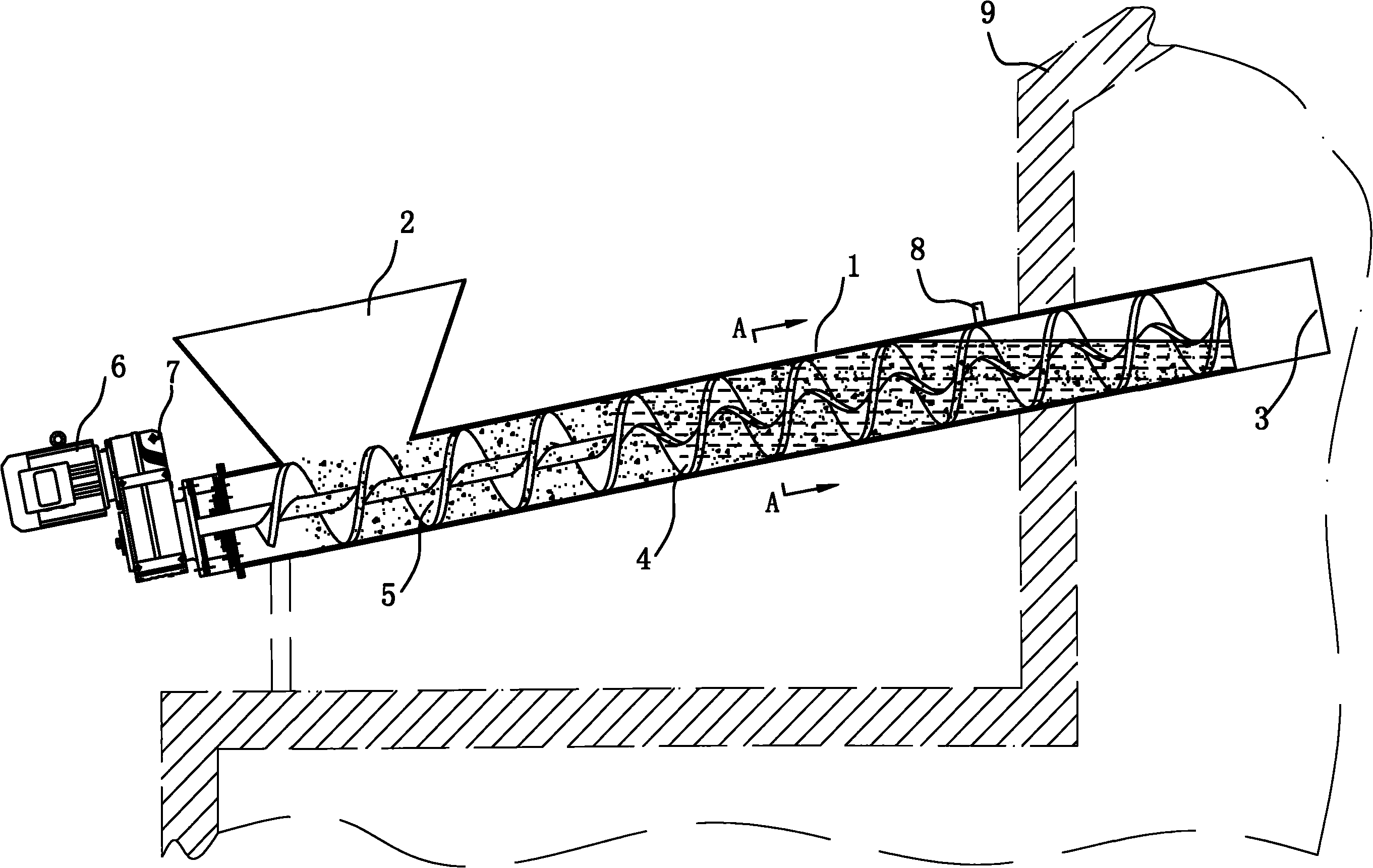
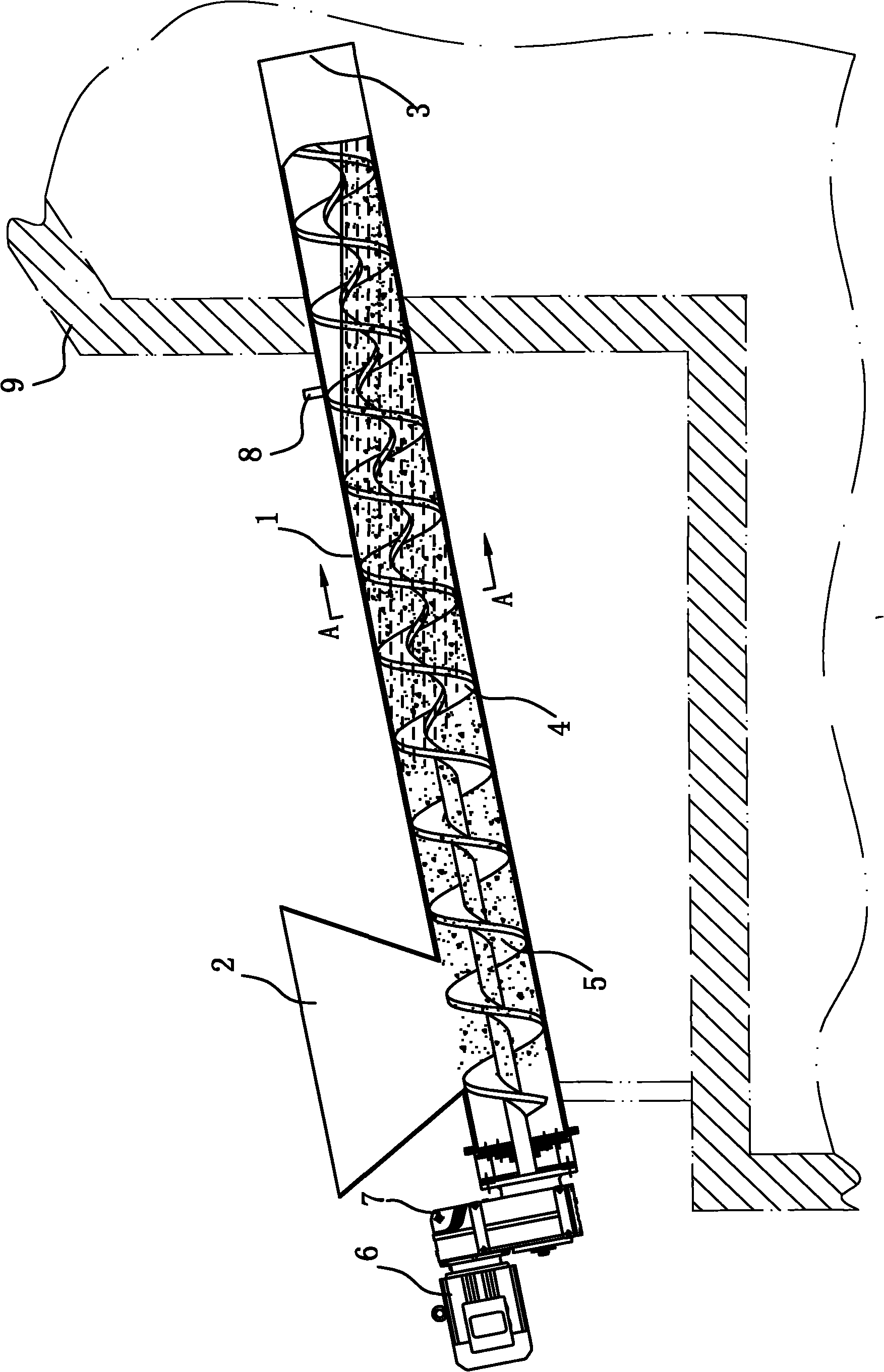
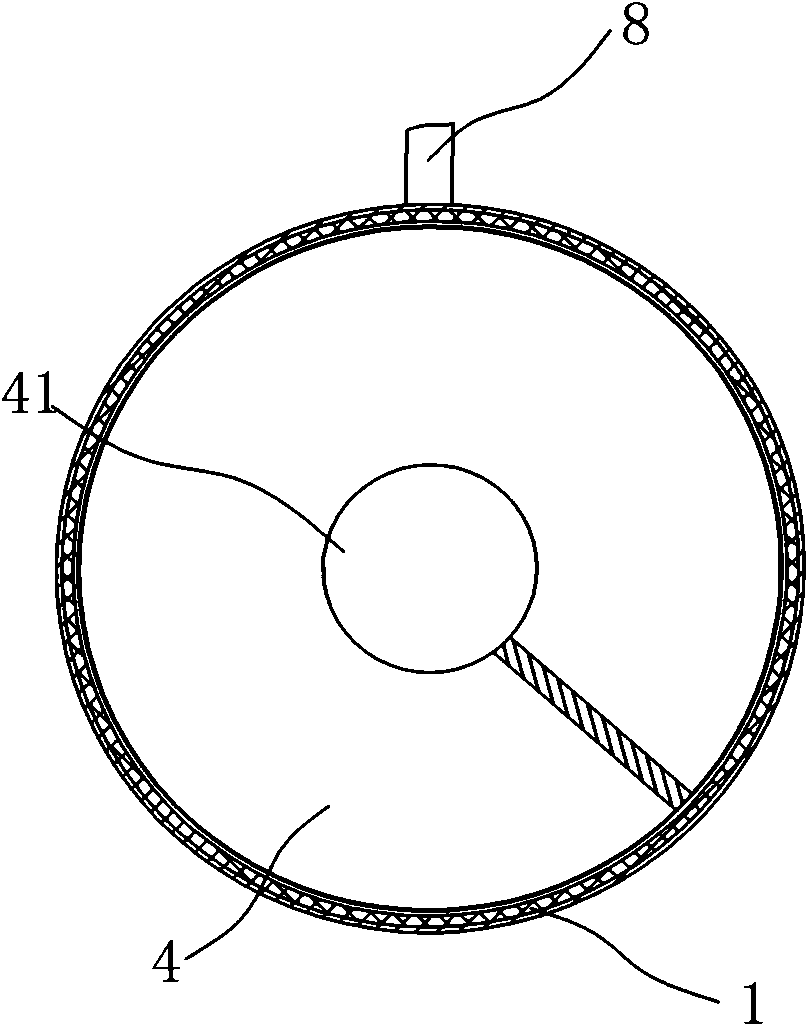
The invention discloses a choke feeding screw conveyor which comprises a cylindrical housing, wherein a feed port and a discharge port are formed on the cylindrical housing, an electric motor is arranged at the end of the feed port of the cylindrical housing, a shaft helical blade and a shaftless helical blade are arranged in the cylindrical housing, the electric motor is in power connection withthe shaft helical blade, the shaft helical blade is connected with the shaftless helical blade, and a sealing water return port is arranged at the back part of the discharge port of the cylindrical housing; due to the adoption of the shaft helical blade, the choke feeding screw conveyor can ensure that materials and water can be pushed forwards, further prevent backflow of the water, and play a water-blocking role; due to the adoption of the shaftless helical blade, the choke feeding screw conveyor can ensure that a sealing water body can not completely enter into a closed tank body; and an inner cavity of the housing at the starting end of the shaftless helical blade is water-sealed, thereby realizing sealing between a feeding machine and the closed tank body, preventing overflow of gas in the tank, having good choke effect and higher conveying speed and further having compact structure.
Description
Barrier feed screw conveyor Technical field The invention relates to a gas barrier feeding device. Background technique In order to prevent the gas in the tank from overflowing during the feeding operation to the closed tank, gas barrier feeding is required. At present, the method of pneumatic conveying is used to realize the barrier feeding. Pneumatic conveying uses compressed gas as the power source and transfers the material through the conveying pipe. It is sent to a sealed tank with high conveying speed and uniform cloth, but it uses a large amount of air and is prone to blockage. Summary of the invention The technical problem to be solved by the present invention is to provide a gas-blocking feed screw conveyor with good gas blocking effect, high conveying speed, and compact structure. In order to solve the above technical problems, the technical solution of the present invention is: a gas-barrier feeding screw conveyor includes a cylindrical shell, the front of the cy...
Claims
Login to View More Application Information
Patent Timeline
 Patent Type & Authority Applications(China)
IPC IPC(8): B65G33/14B65G33/24B65G33/26
Inventor 刘国田张明泉胡明恩
Owner 刘振亮
Features
- R&D
- Intellectual Property
- Life Sciences
- Materials
- Tech Scout
- Unparalleled Data Quality
- Higher Quality Content
- 60% Fewer Hallucinations
Learn More Browse by: Latest US Patents, China's latest patents, Technical Efficacy Thesaurus, Application Domain, Technology Topic, Popular Technical Reports.
© 2025 PatSnap. All rights reserved.Legal|Privacy policy|Modern Slavery Act Transparency Statement|Sitemap|About US| Contact US: help@patsnap.com


