Reinforcement cage lifting device

A steel cage and spreader technology, which is applied in the field of spreaders, can solve problems such as easy-to-deflect steel cage docking and difficulties, and achieve the effects of ensuring progress and quality, easy docking, and verticality

Inactive Publication Date: 2012-12-12
HENAN MINE CRANE
View PDF0 Cites 1 Cited by
  • Summary
  • Abstract
  • Description
  • Claims
  • Application Information

AI Technical Summary

Problems solved by technology

[0003] The purpose of the present invention is to provide a steel cage hanger to solve the problem that the existing steel cage is easy to deflect when hoisting, which makes it difficult to connect the steel cage

Method used


Image

  • Reinforcement cage lifting device
  • Reinforcement cage lifting device
  • Reinforcement cage lifting device

Examples


Embodiment Construction

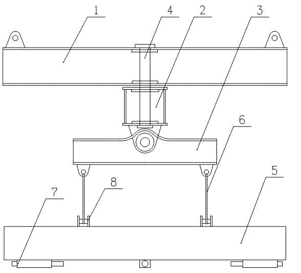
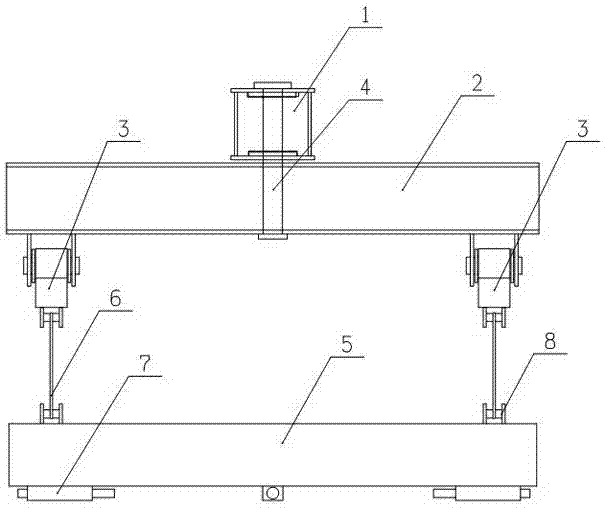
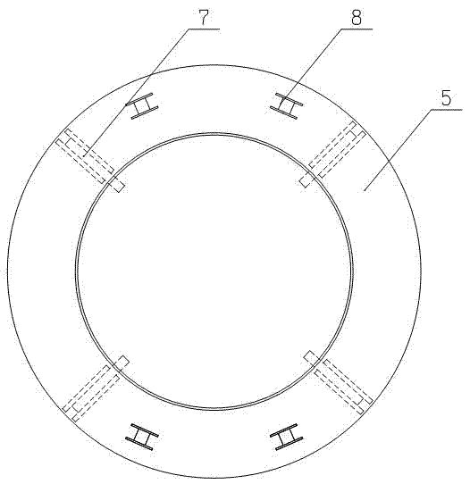
[0012] The specific embodiment of steel cage hanger of the present invention is as figure 1 , figure 2 As shown, it includes an upper beam 1, a middle beam 2, a lower beam 3 and a ring beam 5. The two ends of the upper beam 1 are respectively fixed with lifting lugs for connecting the crane, and the center of the middle beam 2 is vertically rotated. The connecting shaft 4, the upper end of the connecting shaft 4 vertically extends through the center of the upper beam 1, and is rotatably assembled with the upper beam 1, so that there is a symmetrical cross structure between the upper beam 1 and the middle beam 2, and the middle beam 2 The lower parts of the two ends of the two lower beams are symmetrically hinged with the lower beams 3 through the horizontal pin shafts respectively, and the bottoms of the two ends of the two lower beams 3 are symmetrically connected with the pendant 6 respectively, and the ring beam 5 is horizontally suspended on the On the two lower beams 3,...


PUM


Abstract

The invention discloses a reinforcement cage lifting device, which comprises an upper beam, a middle beam, lower beams and an annular beam for connecting a reinforcement cage, wherein the two ends of the upper beam are fixed with a lifting lug for connecting a crane respectively; the middle beam is hinged to the center of the upper beam through a connecting shaft vertically inserted into the middle beam; the lower beams are hinged to the two ends of the middle beam through pin shafts horizontally inserted into the centers of the lower beams respectively; and the annular beam is horizontally suspended on the lower beams by corresponding suspenders. When in use, the reinforcement cage lifting device connects the reinforcement cage to the annular beam in a suspension way, and when the reinforcement cage is jointed, can conveniently drive the reinforcement cage to horizontally rotate, flexibly regulate the vertical angel of the reinforcement cage and ensure the verticality of the reinforcement cage in a jointing process to easily and rapidly finish the jointing of the reinforcement cage, increase the jointing speed of the reinforcement cage and improve the jointing quality of the reinforcement cage by hinging fit among the upper, middle and lower beams, thereby ensuring the progress and quality of pile foundation construction.

Description

technical field [0001] The invention relates to a sling used for hoisting a reinforcement cage in pile foundation construction. Background technique [0002] At present, in the pile foundation construction of bridges, high-rise buildings or high-speed railways, it is necessary to dig deep pile holes first, and then put a reinforcement cage in the pile holes and then pour cement to form a reinforced concrete structure. Because the pile holes are very deep, the reinforcement cages need to be fabricated in sections, and then lowered into the pile holes by a crane, and the main bars on the two reinforcement cages are manually screwed through the connecting sleeves to form a reinforcement skeleton. The existing reinforcement cages are hoisted by ropes or hooks, which are easy to stretch and deform the reinforcement cages. In addition, the reinforcement cages are prone to deflection during the transportation process, making adjustment difficult, and the upper and lower reinforceme...

Claims


Application Information

Patent Timeline
Patent Type & Authority Patents(China)
IPC IPC(8): B66C1/10B66C1/12B66C1/62B66C13/08
Inventor 高明利任海涛
Owner HENAN MINE CRANE
Why Eureka
Try Eureka