Hydraulic chuck for core drilling machines

A technology for hydraulic chucks and core drilling rigs, which is applied to drill pipes, drill pipes, and drilling equipment. It can solve problems such as slippage, deflection of underground torque transmission, and weakened clamping force. It achieves low loss, good economy, and Neutral good effect

Inactive Publication Date: 2011-06-15
ZHANGJIAGANG GUOFENG PROSPECTING MACHINERY
View PDF8 Cites 11 Cited by
  • Summary
  • Abstract
  • Description
  • Claims
  • Application Information

AI Technical Summary

Problems solved by technology

In terms of life, due to the fatigue of the spring, the long-term clamping operation will deform the spring, thereby weakening the original clamping force, and slipping will occur

Method used


Image

  • Hydraulic chuck for core drilling machines
  • Hydraulic chuck for core drilling machines
  • Hydraulic chuck for core drilling machines

Examples


Embodiment Construction

[0027] The hydraulic chuck of the core drill of the present invention will be further described in detail below through specific examples.

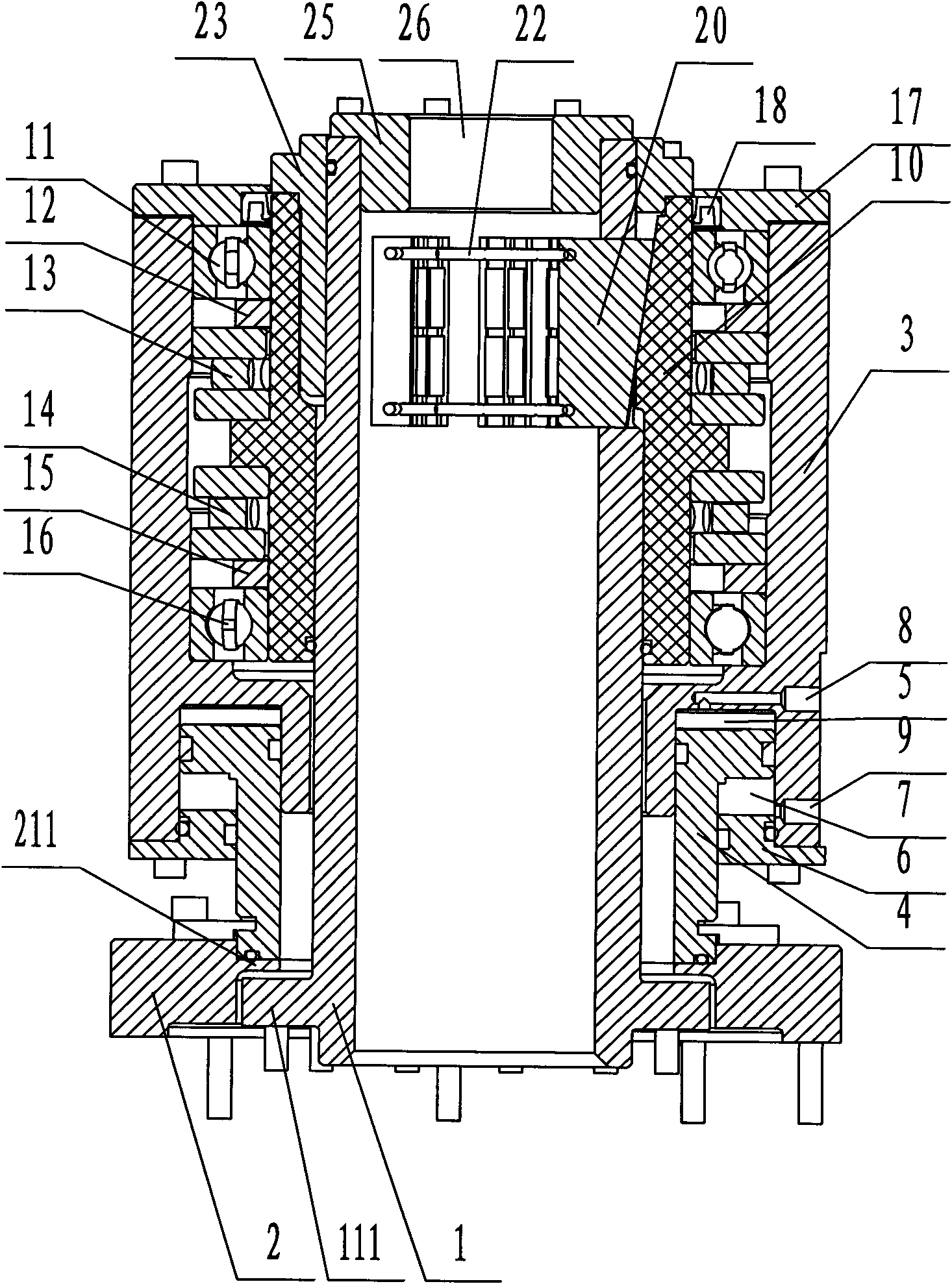
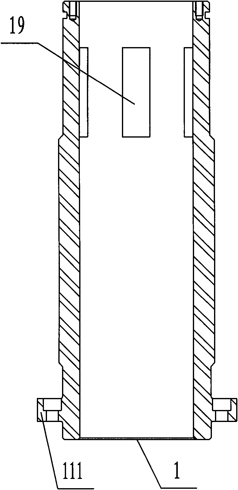
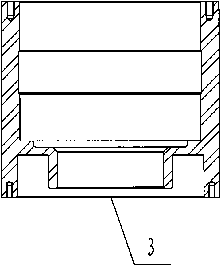
[0028] Such as figure 1 As shown, the hydraulic chuck of a core drilling machine includes a hollow mandrel 1. The lower part of the outer wall of the mandrel 1 is movably arranged in the power head cover 2, and the lower part of the outer wall of the mandrel 1 is provided with a boss 111. A limit block 211 is provided on the power head cover 2 of the power head. The limit block 211 is located above the boss 111 and is used for the axial limit between the spindle 1 and the power head cover 2. A chuck oil cylinder is provided on the outside, and the structure of the chuck oil cylinder is: an outer cylinder liner 3, and the structure of the outer cylinder liner 3 is as image 3 As shown, the inner cylinder liner 4 is movably sleeved in the cavity at the lower end of the outer cylinder liner 3, an upper oil chamber 5 is formed between the outer c...


PUM


Abstract

The invention relates to a hydraulic chuck for core drilling machines, which comprises a mandrel, wherein the lower part of the outer wall of the mandrel is provided with a power-head case cover, and the outside of the mandrel is provided with a chuck cylinder; the chuck cylinder comprises an external cylinder sleeve and an internal cylinder sleeve, and an upper oil cavity is formed between the external cylinder sleeve and the internal cylinder sleeve; the lower end of the external cylinder sleeve is fixed with a lower end cover, and a lower oil cavity is formed between the lower end cover and the external cylinder sleeve as well as the internal cylinder sleeve; the external cylinder sleeve is provided with a first oil hole and a second oil hole, the first oil hole is communicated with the upper oil cavity, and the second oil hole is communicated with the lower oil cavity; the internal cylinder sleeve is fixed with the power-head case cover, a slope sleeve is arranged between the external cylinder sleeve and the mandrel, and a bearing pack is arranged between the slope sleeve and the external cylinder sleeve; an upper end cover is arranged above the bearing pack, and the upper end cover is fixed with the external cylinder sleeve; and at least three slips are arranged in the mandrel, the external end face of each slip is a slope, the external end face of each slip is abutted against the internal end face of the slope sleeve, and the inside of the internal end face of each slip is provided with a return spring. The hydraulic chuck provided by the invention is suitable for various core drilling machines.

Description

Technical field [0001] The invention relates to a chuck for a core drilling machine. Background technique [0002] When the core drilling rig is working, its chuck is used to clamp the drilling tool. The chuck of a traditional core drilling rig is composed of multiple sets of springs, and the drilling tool is clamped by spring force. This method has the following problems in clamping: [0003] Structurally, after the spring-type chuck is clamped, the entire outer ring of the chuck is driven to rotate together, so that the system torque is wasted, and the high-speed rotation of the exposed outer ring will bring danger to the construction. In terms of clamping force, the clamping force of a spring-type chuck depends on the spring, and its size cannot be adjusted. In terms of life, due to the fatigue of the spring, long-time clamping operation will deform the spring, thereby weakening the original clamping force, slipping during drilling, and the loosening of the clamping will gener...

Claims


Application Information

Patent Timeline
IPC IPC(8): E21B19/10
Inventor 黎毅力
Owner ZHANGJIAGANG GUOFENG PROSPECTING MACHINERY
Why Eureka
Try Eureka