Multi-pump concurrent flow hydraulic system for crane and concurrent valve bank

A confluence valve and hydraulic pump technology, applied in cranes, fluid pressure actuating devices, mechanical equipment, etc., can solve problems such as cost reduction, limited pressure, and large specific weight, and achieve the effects of cost reduction, simplified line connection, and quantity reduction

Inactive Publication Date: 2011-06-15
XUZHOU HEAVY MASCH CO LTD
View PDF7 Cites 29 Cited by
  • Summary
  • Abstract
  • Description
  • Claims
  • Application Information

AI Technical Summary

Problems solved by technology

[0004] The cost of the power source of the hydraulic system of the crane has a relatively large proportion in the cost of the whole crane. As mentioned above, in the prior art, the oil pump system for getting off the car needs to be equipped with five oil pumps in total, which is a large number. Obviously, the manufacturing cost of the corresponding main engine Second, the large number of oil pumps increases the difficulty of ge

Method used


Image

  • Multi-pump concurrent flow hydraulic system for crane and concurrent valve bank
  • Multi-pump concurrent flow hydraulic system for crane and concurrent valve bank
  • Multi-pump concurrent flow hydraulic system for crane and concurrent valve bank

Examples


Example Embodiment

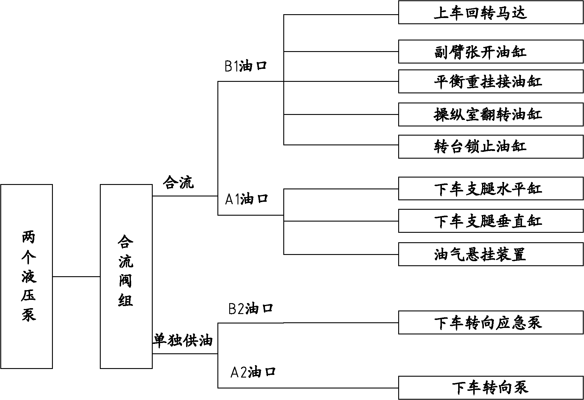
[0024] The core of the present invention is to provide a confluence valve group, which can make the pressure oil of two hydraulic pumps merge to the same oil outlet for corresponding load work, thereby reducing the number of hydraulic pumps in the hydraulic system. Another core of the present invention is to provide a multi-pump confluence hydraulic system for cranes.

[0025] In order to enable those skilled in the art to better understand the solution of the present invention, the present invention will be further described in detail below with reference to the accompanying drawings and specific embodiments.

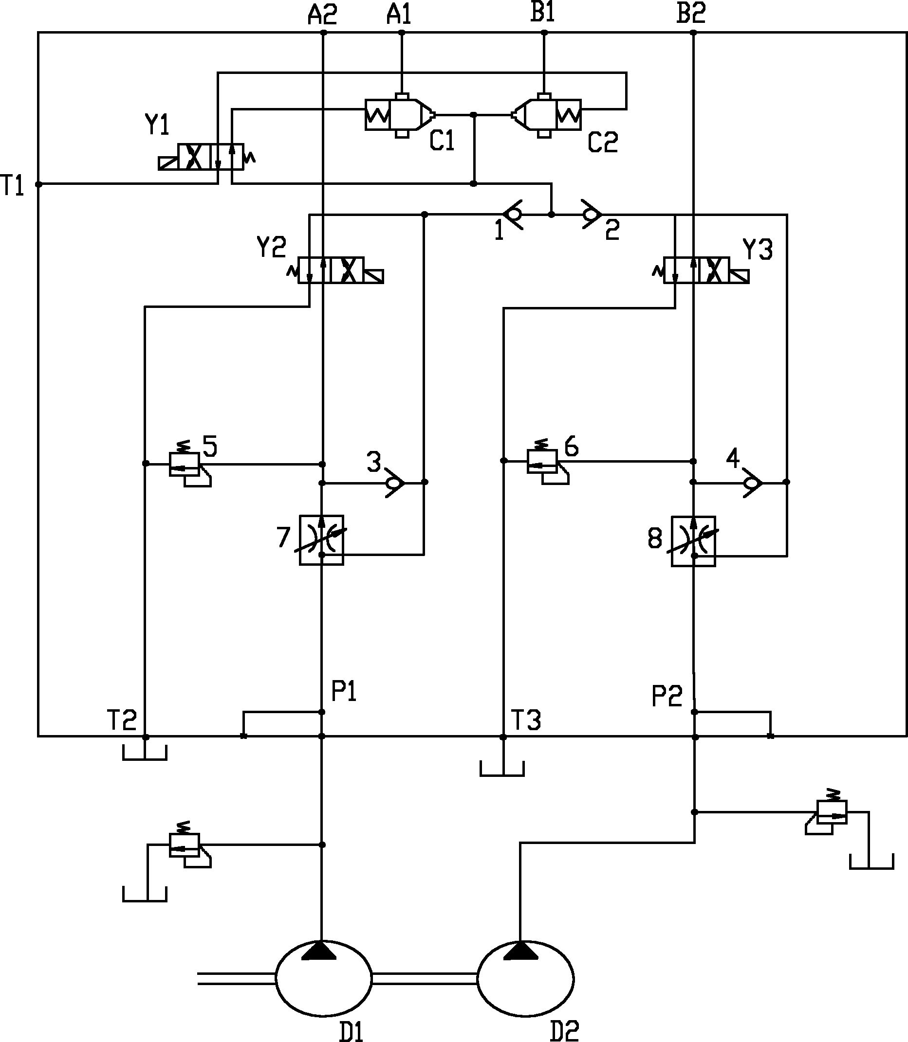
[0026] Please refer to figure 1 , figure 1 It is a working principle diagram of a specific implementation of the confluence valve group provided by the present invention.

[0027] The valve body of the converging valve group provided by the invention has a first oil inlet P1 and a second oil inlet P2. The first oil inlet P1 is connected with the pump oil port of the first hyd...


PUM


Abstract

The invention discloses a concurrent valve bank which is provided with a first oil outlet, a second oil outlet, a first oil inlet, a second oil inlet and an oil return port, and the valve body of the concurrent valve bank is internally provided with a first control valve, a second control valve and a first reversing valve; the on and off of the first control valve and the second control valve arecontrolled through the switching of the working position of the first reversing valve, so that the oil liquid which enters from the first oil inlet and the second oil inlet can flow out of a second main oil port of the first control valve and the second control valve, and then enters the load which is communicated with the first oil outlet and the second oil outlet. Thus the oil liquid output from two hydraulic pumps concurrently flows to the same oil outlet by virtue of the concurrent flow bank; and because the concurrent flow quantity of the oil liquid is greater, a larger amount of load work can be satisfied simultaneously, the number of the hydraulic pumps in a hydraulic system is reduced, the manufacturing cost is lowered, and the hydraulic system is simplified. The invention also discloses a multi-pump concurrent flow hydraulic system for a crane.

Description

technical field [0001] The invention relates to the technical field of construction machinery, in particular to a multi-pump confluence valve group for a crane. The present invention also relates to a multi-pump confluence hydraulic system comprising the above confluence valve group. Background technique [0002] Hydraulic control technology is widely used in the field of construction machinery technology. Taking cranes as an example, the hydraulic system in cranes has become an important source of control power. [0003] At present, the oil pump in the hydraulic system of the medium-tonnage wheeled crane is usually placed under the car. The steering of getting off the car is usually controlled by two oil pumps, one is the normal oil supply pump and the other is the steering emergency pump; in addition, the oil-pneumatic suspension composed of accumulators and suspension cylinders with shock absorber functions is used to improve the ride comfort of the vehicle The system a...

Claims


Application Information

Patent Timeline
IPC IPC(8): B66C23/62F15B13/02
Inventor 刘邦才曹立峰游焕强
Owner XUZHOU HEAVY MASCH CO LTD
Why Eureka
Try Eureka