Defrosting detector and defrosting control method based on frost layer thickness

A detector and frost layer technology, which is applied in the field of air source heat pump control, can solve the problems of sensitive components being easily affected by the outdoor environment, inaccurate defrosting judgment, and difficulties in practical application, and achieve simple structure, high reliability, and cheap materials Effect

Inactive Publication Date: 2011-06-15
HARBIN INST OF TECH
View PDF4 Cites 17 Cited by
  • Summary
  • Abstract
  • Description
  • Claims
  • Application Information

AI Technical Summary

Problems solved by technology

[0013] The purpose of the present invention is to solve the inaccurate defrosting judgment existing in the indirect method of defrosting the air source heat pump; the theory is beautiful but the practical application is difficult; the cost is too high, so it is difficult to popularize; some sensitive compon

Method used


Image

  • Defrosting detector and defrosting control method based on frost layer thickness
  • Defrosting detector and defrosting control method based on frost layer thickness
  • Defrosting detector and defrosting control method based on frost layer thickness

Examples


specific Embodiment approach 1

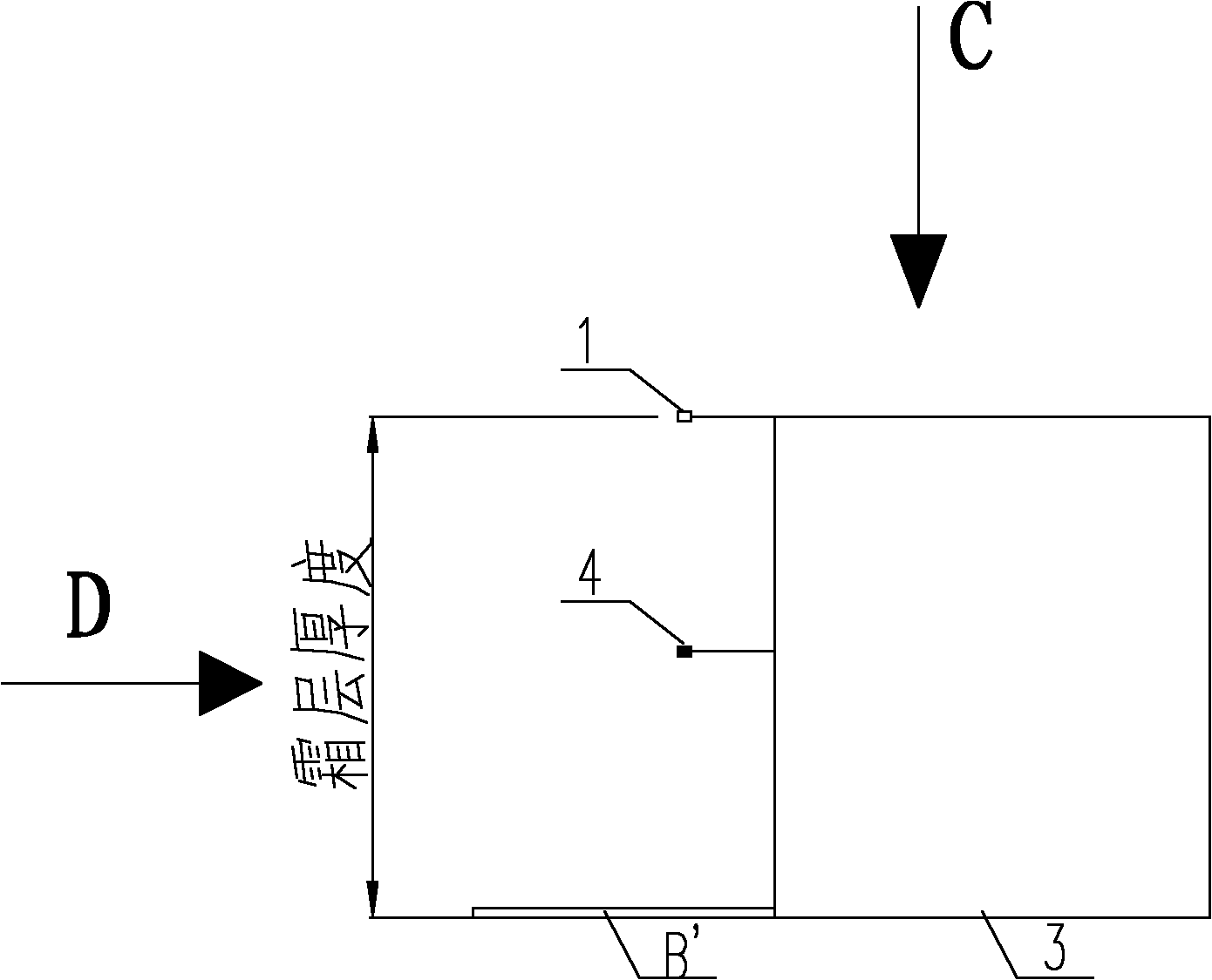
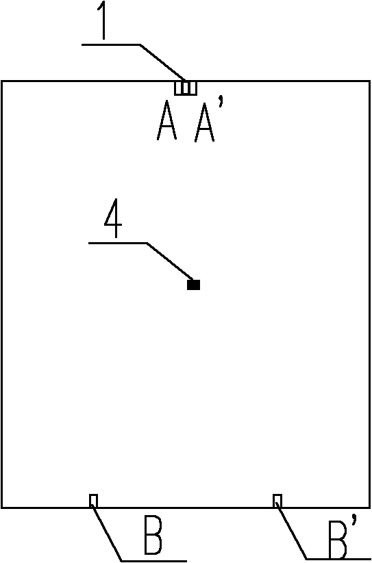
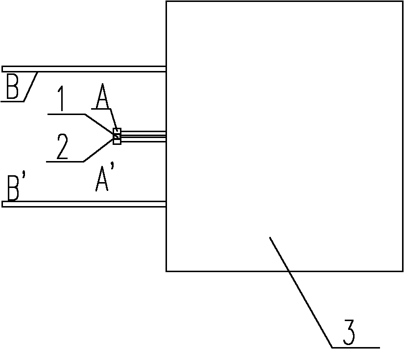
[0039] Specific implementation mode one: the following combination Figure 1 to Figure 6 Describe this embodiment, a defrosting detector based on the thickness of the frost layer described in this embodiment, which includes a heating resistor 1, a heat-insulating plastic body 3, a temperature sensor 4, a first electrode pair A-A', a second electrode For BB', power supply, defrost detector start switch K1, defrost start switch K2, intermittent switch K3, defrost start resistor R1 and defrost judgment completion resistor R2, the outer surface of heating resistor 1 is coated with insulating layer 2 , the first electrode pair A-A' is respectively arranged on the left and right end faces of the heating resistor 1, the heating resistor 1 and the second electrode pair BB' are located outside one side of the heat-insulating plastic body 3, and are mechanically connected to it, the heating resistor 1 is arranged on the top of the side, and the second electrode pair BB' is arranged on t...

specific Embodiment approach 2

[0056] Specific embodiment two: This embodiment is based on the defrosting control method of the defrosting detector based on the thickness of the frost layer described in the first embodiment, the method is:

[0057] The defrost detector does not work: when the air source heat pump is in cooling operation, the defrost detector does not work, and the defrost detector start switch K1, defrost start switch K2, and intermittent switch K3 are disconnected;

[0058] Defrost detector activation state: when the temperature detected by the temperature sensor 4 is between -12°C and 1°C, the defrost detector start switch K1 is closed, the intermittent switch K3 is intermittently closed, and the defrost detector is started;

[0059] The defrosting start state of the air source heat pump: when the intermittent switch K3 is closed, the heating resistor 1 is in a closed loop, and the heat generated by the heating resistor 1 will melt the frost on the surface of the insulating layer 2 outside...


PUM


Abstract

The invention discloses a defrosting detector and a defrosting control method based on the frost layer thickness, belonging to the field of air source heat pump control, and aiming at solving the problems of the inaccurate judgement of defrosting by adopting an indirect method for the existing air source heat pump and over high cost. According to the invention, an insulative layer is coated at the outer surface of a heating resistor, and first electrode pairs A-A' are arranged at the left and right of the heating resistor. The defrosting control method is as follows: in non-working state of the defrosting detector: disconnecting all switches; in the starting up state of the defrosting detector: starting the defrosting detector at the temperature of minus 12 DEG C- 1 DEG C the switching off, intermittently the switching on and off; in the starting state of defrosting: heating the resistor to work, conducting the first electrolde pairs A-A' by a frost melting water film, and outputting defrosting signals; in the defrosting state of the air source heat pump: conducting a second electrode pair B-B' by the frost melting at the surface of the fin; and in the defrosting suspending state of the defrosting detector: determining that the defrosting is finished when the output voltage signal is zero.

Description

technical field [0001] The invention relates to a defrosting detector based on frost layer thickness and a defrosting control method, belonging to the field of air source heat pump control. Background technique [0002] The existing defrosting control strategies for air source heat pumps are divided into two types: indirect method and direct method. Most of the existing defrosting methods are indirect methods, mainly including the following: [0003] 1. Timing control method, time temperature method. This type of method sets the defrosting time to a fixed value, which cannot take into account the changes in ambient temperature and humidity, and cannot accurately grasp the defrosting entry point, which is prone to misoperation, and this method is more sensitive to the installation position of the temperature sensor. The common installation in the middle may easily lead to inaccurate judgment of the end of frosting and unclean defrosting. [0004] 2. Self-correcting defrost...

Claims


Application Information

Patent Timeline
IPC IPC(8): F25B47/00F25B49/02G01B7/06
Inventor 姜益强姚杨邱国栋董建锴
Owner HARBIN INST OF TECH
Why Eureka
Try Eureka