System for testing linear motor characteristics

A characteristic test and linear motor technology, applied in the direction of motor generator test, asynchronous induction clutch/brake, etc., can solve the problems of non-continuous change, single-direction test loading force, etc., to achieve convenient operation, eliminate loading force fluctuations, and reliability sex high effect

Active Publication Date: 2011-06-15
HARBIN INST OF TECH
View PDF4 Cites 20 Cited by
  • Summary
  • Abstract
  • Description
  • Claims
  • Application Information

AI Technical Summary

Problems solved by technology

[0005] The purpose of the present invention is to provide a linear motor characteristic test system in order to solve the problem th...

Method used


Image

  • System for testing linear motor characteristics
  • System for testing linear motor characteristics
  • System for testing linear motor characteristics

Examples


specific Embodiment approach 1

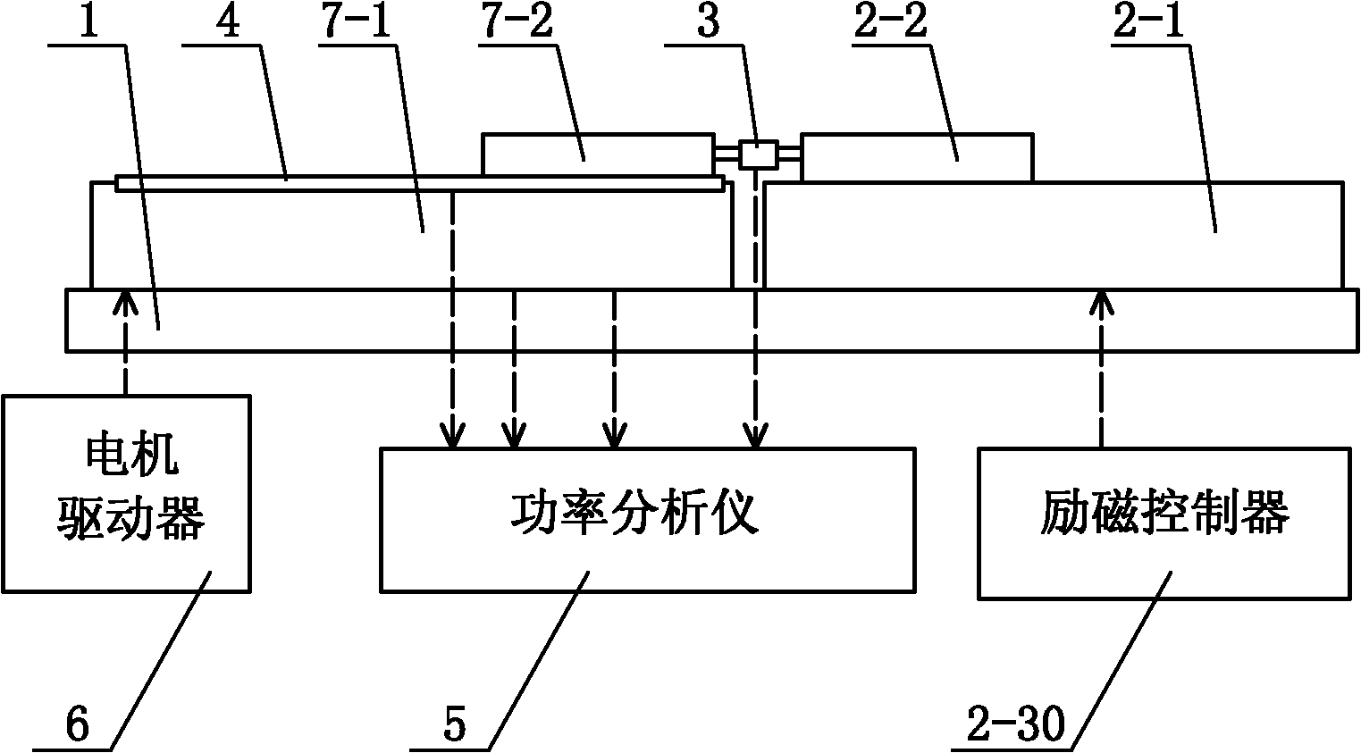
[0029] Specific implementation mode one: the following combination Figure 1 to Figure 7 Describe this embodiment, this embodiment is made up of system platform 1, linear electromagnetic damper, force sensor 3, speed sensor 4, power analyzer 5 and motor driver 6,

[0030] The motor stator 7-1 of the motor under test and the damper stator 2-1 of the linear electromagnetic damper are set on the system platform 1 at the same time, and the relative positions of the motor stator 7-1 and the damper stator 2-1 remain constant. Change,

[0031] The power output end of the motor driver 6 is connected to the armature winding input end of the motor under test, and the armature winding output end of the motor under test is respectively connected to the current input end and the voltage input end of the power analyzer 5,

[0032] The force sensor 3 is used to detect the interaction force between the motor mover 7-2 of the motor under test and the damper mover 2-2 of the linear electromagn...

specific Embodiment approach 2

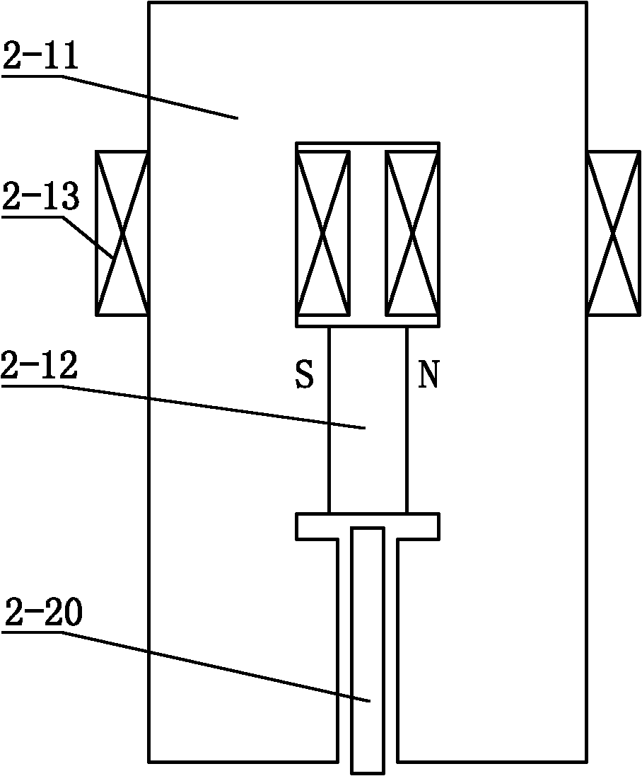
[0044] Specific implementation mode two: the following combination figure 2 Describe this embodiment. This embodiment is a further description of Embodiment 1. The linear electromagnetic damper is a double-sided single-primary structure.

[0045] The iron core 2-11 forms a gate-shaped structure by a horizontal section and two vertical core columns. The middle part of the horizontal section is wound with an excitation coil 2-13 or the upper section of each vertical core is wound with an excitation coil 2-13, two The permanent magnet 2-12 is clamped between the middle sections of the vertical core columns, the secondary 2-20 is arranged between the inner side walls of the lower section of the two vertical core columns, and the secondary 2-20 is connected to the lower section of the two vertical core columns. Air gaps are respectively formed between the inner side walls. Other components and connections are the same as those in Embodiment 1.

[0046] figure 2 The excitation ...

specific Embodiment approach 3

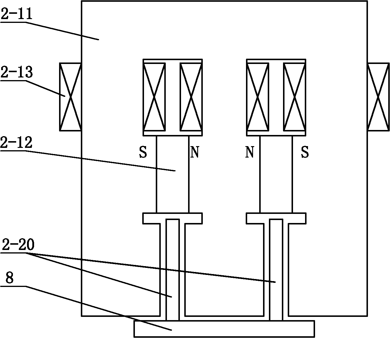
[0048] Specific implementation mode three: the following combination image 3 Describe this embodiment. This embodiment is a further description of Embodiment 1. The linear electromagnetic damper is a double-sided single-primary parallel structure.

[0049]The iron core 2-11 forms a comb structure of N-1 teeth by a horizontal section and N vertical columns, N is a natural number greater than or equal to 3, and the horizontal section between each adjacent two vertical columns An excitation coil 2-13 is wound in the middle or an excitation coil 2-13 is wound on the upper section of each vertical core column, and a permanent magnet 2-12 is clamped between the middle sections of each adjacent two vertical core columns, and each adjacent A secondary 2-20 is set between the inner walls of the lower section of the two vertical columns, and air gaps are formed between each secondary 2-20 and the inner walls of the vertical columns on both sides, N-1 secondary Stages 2-20 are fixedly ...


PUM


Abstract

The invention provides a system for testing linear motor characteristics with linear linear device, which belongs to the technical field of motors and solves the problems that the conventional system for testing the linear motor characteristics can be used for testing in a single direction and a loading force cannot be changed continuously. A stator of the motor and a stator of a linear electromagnetic damper are simultaneously arranged on a system platform; the power output end of a motor driver is connected with the armature winding input end of a tested motor; the armature winding output end of the tested motor is connected with the current input end and the voltage input end of a power analyzer respectively; a force sensor is used for detecting a mutual acting force between a rotor of the tested motor and a rotor of the linear electromagnetic damper; the force signal output end of the force sensor is connected with the force signal input end of the power analyzer; a speed sensor is used for detecting the speed of the rotor of the motor or the stator of the damper; the speed signal output end of the speed sensor is connected with the speed signal input end of the power analyzer; and the linear electromagnetic damper consists of a primary, a secondary and an excitation controller. The invention is used as the test system of the linear motor.

Description

technical field [0001] The invention relates to a linear motor characteristic testing system, which belongs to the technical field of motors. Background technique [0002] In the field of modern processing industry, many occasions such as laser cutting, high-speed grinding machines, precision lathes and machining centers require high-speed and high-precision linear motion. The traditional method can only use intermediate links such as rotating motors and ball screws to obtain linear motion. Movement, which inevitably has disadvantages such as large inertia, large friction, and backlash. In recent years, with the advancement of linear motor technology, more and more occasions have begun to directly apply it to obtain linear motion. Due to the use of direct drive technology, linear motors have the advantages of fast speed, high acceleration, high positioning accuracy, long stroke and fast dynamic response, which just meet the requirements of high-speed precision machining tec...

Claims


Application Information

Patent Timeline
IPC IPC(8): G01R31/34H02K49/04
Inventor 寇宝泉李立毅金银锡潘东华
Owner HARBIN INST OF TECH
Why Eureka
Try Eureka