Method for installing reactor core catcher of nuclear power station

A core capture and installation method technology, applied in nuclear power generation, reactors, nuclear engineering, etc., can solve problems such as poor construction environment, narrow working space, difficult construction and heavy workload

Active Publication Date: 2011-06-15
CHINA NUCLEAR IND 23 CONSTR
View PDF3 Cites 39 Cited by
  • Summary
  • Abstract
  • Description
  • Claims
  • Application Information

AI Technical Summary

Problems solved by technology

[0003] The four parts of the core catcher are installed on the bottom plate of the reactor shaft from top to bottom. If the functions of these four parts are guaranteed by suitable installation techniques, the working space in the reactor shaft is narrow, especially if there is In the case of inwardly extending concrete cantilever beams, the construction environment is poor. It can be seen that in order to realize the function of the core trap, the construction difficulty and workload are quite large

Method used


Image

  • Method for installing reactor core catcher of nuclear power station
  • Method for installing reactor core catcher of nuclear power station
  • Method for installing reactor core catcher of nuclear power station

Examples


Embodiment Construction

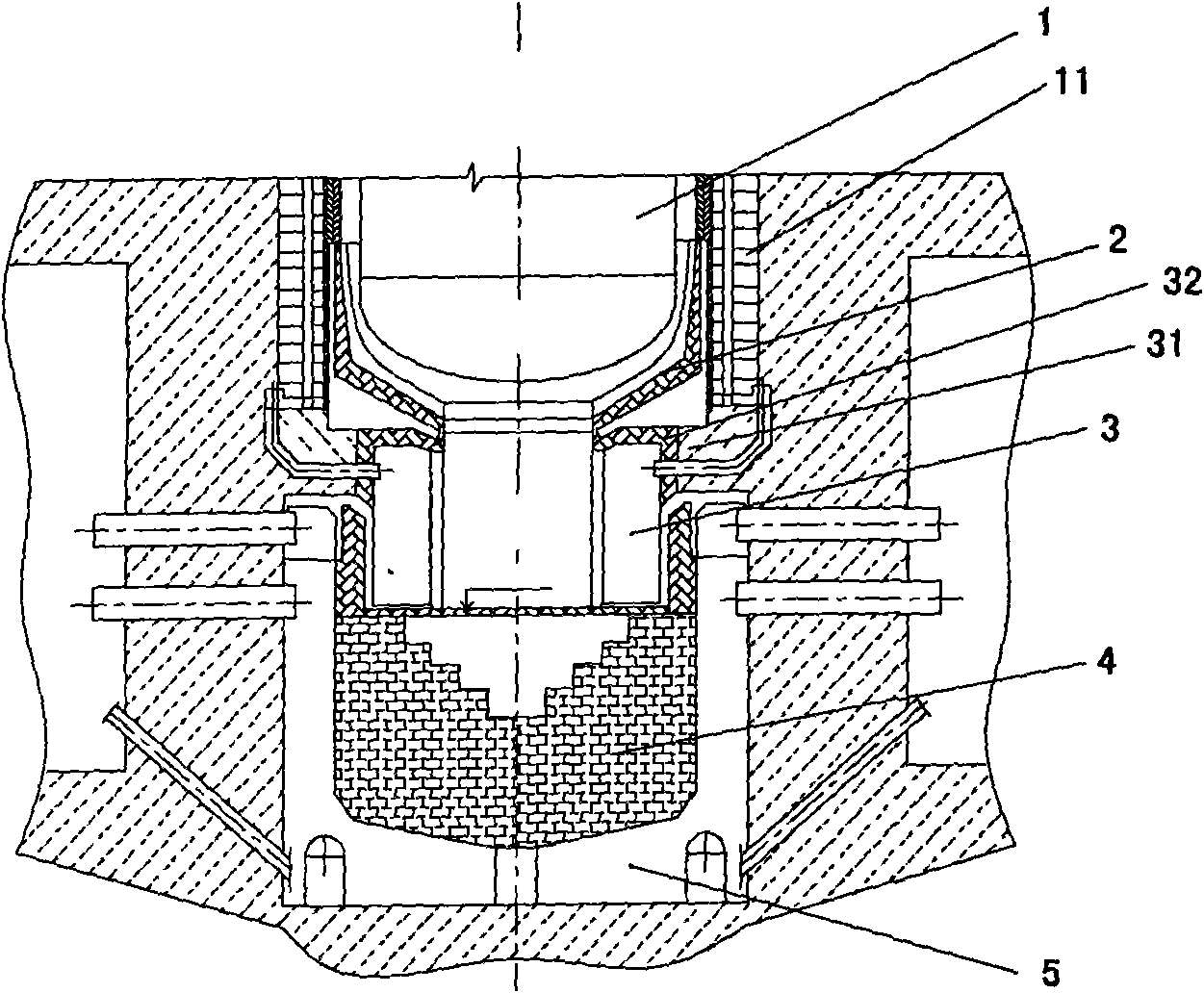
[0019] figure 1 is a component layout diagram of a core catcher for a nuclear power plant according to an embodiment of the present invention. The core traps are arranged from top to bottom along the pressure vessel 1 to the bottom of the reactor shaft. They are: lower base plate 2, ventilation system 3, hanging basket with filling 4, segmental heat exchanger 5.

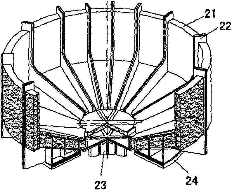
[0020] The lower bottom plate 2 is designed in a funnel shape to completely contain the bottom of the pressure vessel 1, such as figure 2 shown. The top of lower base plate 2 links to each other with the lower insulation layer of dry protection 11, so just guarantees that molten slag can not directly work on dry protection and flows in the hanging basket 4 of band filling along the lower base plate 2 of funnel type.

[0021] The ventilation system 3 has a ventilation and cooling function for the reactor shaft equipment under normal operation of the reactor. In the working state of the core catcher, it is equival...


PUM


Abstract

The invention provides a method for reliably installing a reactor core catcher in a narrow reactor vertical shaft, comprising the steps of: (1) installing a forging heat exchange device on a bottom plate of the reactor vertical shaft; (2) installing a hanging basket with fillers; and (3) installing a ventilation system and a lower bottom plate, wherein the step 1 for installing the forging heat exchange device further comprises the steps of: (1a) placing a plurality of forgings of a heat exchange device on the foundation of the reactor vertical shaft in advance, and confirming the actual respective positions of the forgings; (1b) installing a central fixing member and a supporting ribbed plate in the center of the vertical shaft; (1c) installing forgings on two sides of the ribbed plate according to the actual positions, and respectively fixing the forgings on the wall and the bottom plate of the vertical shaft through connecting pieces; and (1d), sequentially installing and welding the supporting ribbed plate and the forgings of the heat exchange device according to certain sequence. Accordingly, the method provided by the invention is favorable for greatly lowering the construction difficult and the construction workload at the same time of ensuring that all the parts of the reactor core capturer are safe and effective.

Description

technical field [0001] The invention relates to a method for installing a core catcher used in a nuclear power plant. Background technique [0002] The core trap is designed by the St. Petersburg Design Institute in Russia. It is an original design in the design of nuclear power plants in the world, and it is applied to Tianwan Nuclear Power Plant for the first time. The core trap is used to deal with a hypothetical severe accident in which the core melts and burns through the pressure vessel. The core catcher is arranged at the lower part of the pressure vessel in the reactor shaft. When the molten core and pressure vessel materials fall into the core trap, the melt reacts chemically with the sacrificial material in the trap, and the decay heat is taken away by the heat exchanger of the core trap, and the melt Stay in the trap, so as to ensure the effectiveness of the containment sealing barrier, so as to achieve the purpose of safety. The core catcher can be divided int...

Claims


Application Information

Patent Timeline
Patent Type & Authority Applications(China)
IPC IPC(8): G21C9/016
CPCY02E30/40Y02E30/30
Inventor 不公告发明人
Owner CHINA NUCLEAR IND 23 CONSTR
Why Eureka
Try Eureka