Current transformer-based light-emitting diode (LED) driving circuit
A technology of current transformer and LED drive, applied in electric lamp circuit arrangement, electric light source, lighting device, etc., can solve the problems of affecting application, increasing control difficulty, affecting steady-state gain of converter, etc., and achieving the effect of reducing production cost
Active Publication Date: 2011-06-15
盐城市盐南高新区都市产业发展有限公司
View PDF7 Cites 6 Cited by
- Summary
- Abstract
- Description
- Claims
- Application Information
AI Technical Summary
Problems solved by technology
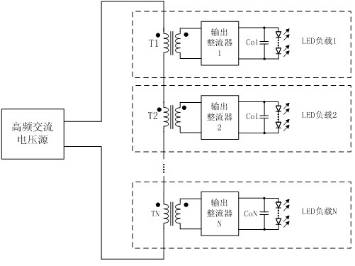
Although this technology is feasible in principle, there are some shortcomings in practical application, which affect its practical application, such as: (1) The discreteness of transformer excitation inductance will affect the current sharing degree of multiple output currents
(2) When a certain load is short-circuited, since only the capacitor is filtered, the corresponding transformer of this road is equivalent to a short-circuit, resulting in a change in the total excitation inductance connected in series on the primary side, thereby affecting the steady-state gain of the converter and increasing the Difficult to control, thus seriously reducing the reliability of the converter
Method used
View moreImage
Smart ImageViewing Examples
Examples
Embodiment Construction
Login to View More PUM
 Abstract
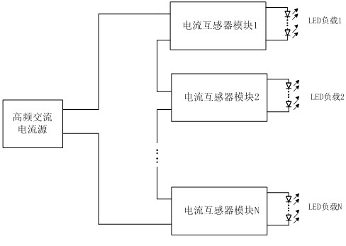
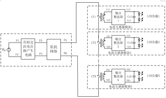
The invention discloses a current transformer-based light-emitting diode (LED) driving circuit. The existing driving circuit is relatively complex and is high in cost. The current transformer-based LED driving circuit comprises a high frequency alternating current (AC) source and N current transformer modules; each current transformer module comprises a current transformer, an output rectifier and an output capacitor. An output end of the high frequency AC source is connected with one end of the current transformer primary winding in the first current transformer module. All the current transformer primary windings are connected in series one by one until the other input end of the current transformer module N-1 is connected with an input end of the current transformer module N and the other end of the current transformer primary winding in the N-th current transformer current is connected with the other output end of the high frequency current source. A positive output end of each current transformer module is connected with a positive input end loaded by the corresponding LED, and a negative output end of the current transformer module is connected with a negative input end loaded by the corresponding LED. The current transformer-based LED driving circuit realizes modular production easily and reduces the production cost.
Description
LED drive circuit based on current transformer technical field The invention belongs to the technical field of switching power supplies and relates to an LED driving circuit. Specifically, it is a drive circuit that realizes multi-channel LED load current balance through current transformers. Background technique LEDs need to be driven by constant current. In some high-power lighting applications, LEDs usually need to be used in series or in parallel. When LEDs are used in parallel, each channel needs constant current control, which increases the circuit cost. Therefore, for LEDs, direct series connection is the easiest way, but if too many LEDs are connected in series, on the one hand, the output voltage of the driver will be higher, which increases the cost of circuit components; on the other hand, if one of the LEDs fails, the entire string will The LED light fails, so it's not very reliable from a system point of view. One technology is to use multiple high-frequenc...
Claims
Login to View More Application Information
Patent Timeline
 IPC IPC(8): H05B37/02
Inventor 谢小高吕强王加莲
Owner 盐城市盐南高新区都市产业发展有限公司
Features
- R&D
- Intellectual Property
- Life Sciences
- Materials
- Tech Scout
- Unparalleled Data Quality
- Higher Quality Content
- 60% Fewer Hallucinations
Learn More Browse by: Latest US Patents, China's latest patents, Technical Efficacy Thesaurus, Application Domain, Technology Topic, Popular Technical Reports.
© 2025 PatSnap. All rights reserved.Legal|Privacy policy|Modern Slavery Act Transparency Statement|Sitemap|About US| Contact US: help@patsnap.com


