Remote control type fire extinguishing apparatus for high-rise building

A remote control, high-rise building technology, applied in fire rescue and other directions, can solve problems such as affecting fire fighting, losing fire fighting period, and large fire fighting water consumption, and achieving the effect of protecting personal safety.

Inactive Publication Date: 2011-06-22
范伟林
View PDF4 Cites 15 Cited by
  • Summary
  • Abstract
  • Description
  • Claims
  • Application Information

AI Technical Summary

Problems solved by technology

[0003] (1) The best rescue time for firefighting in high-rise buildings is at the initial stage of fire. After a high-rise building catches fire, the fire spreads quickly. If the fire can be effectively controlled in the early stage of fire, the loss can be minimized. However, firefighters generally cannot Can rush to the scene to put out the fire in the early stage of the fire, and lose the best fire fighting period
[0004] (2) High-altitude fire-fighting devices such as fire-fighting ladders have limited ability to fight fires at high altitudes, and are not easy to approach high-rise fire points, and cannot extinguish fires above the limit of the fire-fighting ladder vehicle
[0005] (3) High-rise buildings have a large amount of water for firefighting, and water supply is difficult, while the amount of firefighting water for extinguishing, cooling, and controlling the spread of fire is quite large, but the water provided by fire trucks is limited, which also affects firefighting
[0006] (4) This traditional fire extinguishing method poses a great threat to the personal safety of firefighters

Method used


Image

  • Remote control type fire extinguishing apparatus for high-rise building
  • Remote control type fire extinguishing apparatus for high-rise building
  • Remote control type fire extinguishing apparatus for high-rise building

Examples


Embodiment 1

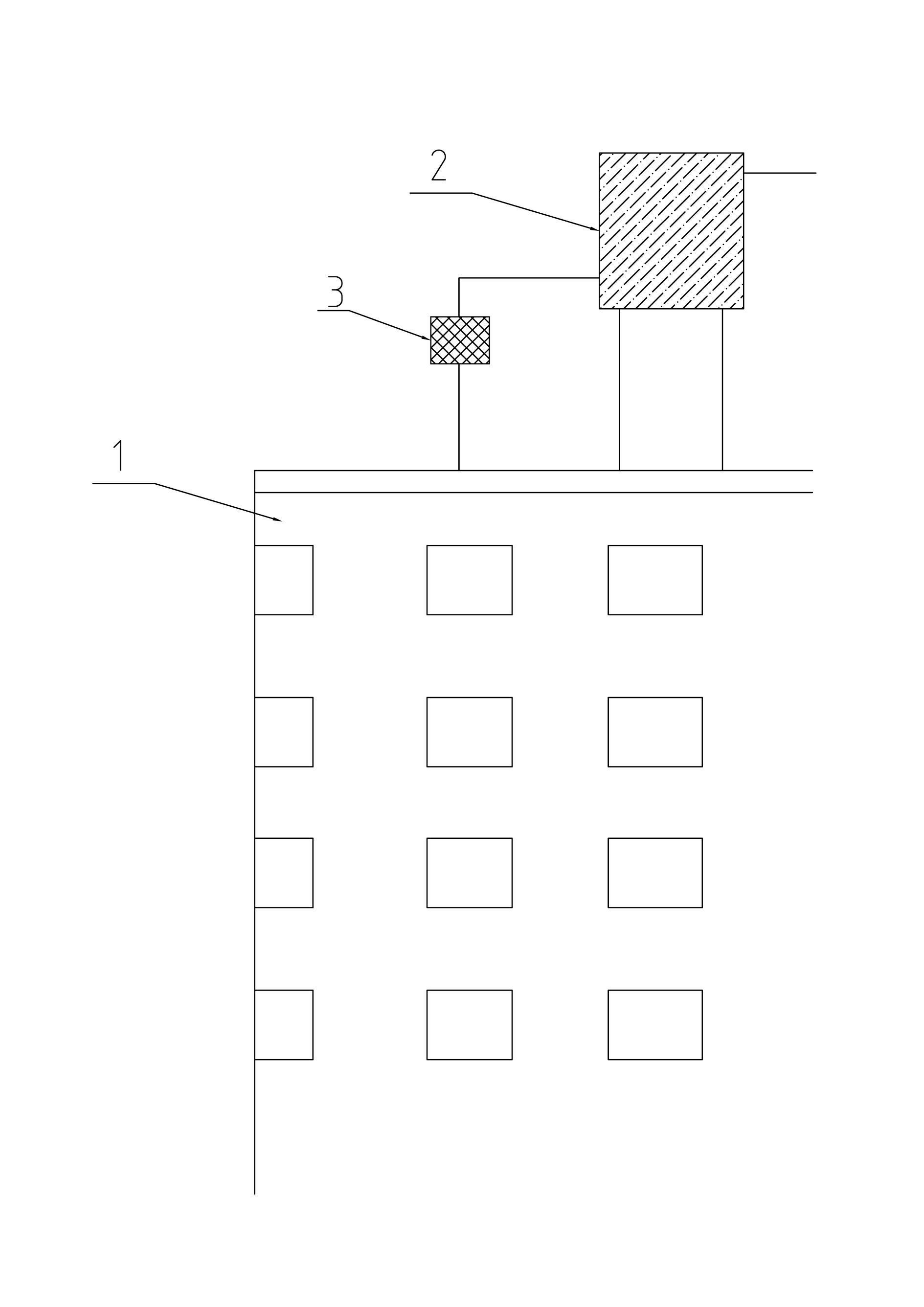
[0031] Such as Figure 1-2 As shown, the water tank 2 is arranged on the top of the building 1, and the pressurized water pump 2 is housed, and the multi-section telescopic arm 6 that can control the action through the telescopic arm control line 21 expands and contracts laterally along the building 1, and one end thereof is connected to the building 1. The telescopic base 5 at the top is connected, and the other end is provided with a nozzle 8 connected to the water tank 2, and at the junction of the multi-section telescopic arm 6 and the telescopic base 5, there is a rotary that can make the multi-section telescopic arm 6 rotate around the telescopic base. Mechanism 13, multi-section telescopic arm 6 side is equipped with camera 7, and telescopic arm control line 21 is connected to the hoisting mechanism 4 that can be remotely controlled that is arranged on building 1 top, and is controlled telescopic by hoisting mechanism 4.

Embodiment 2

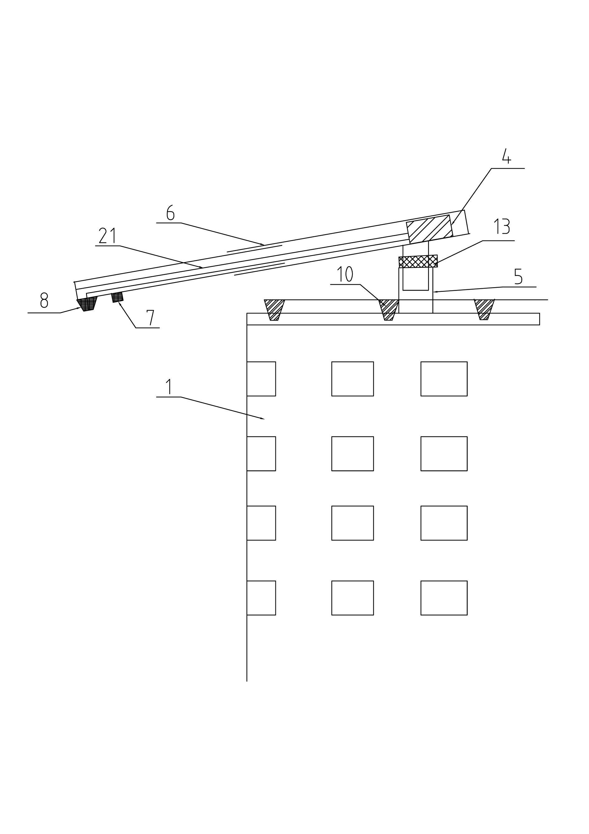
[0033] Such as image 3 As shown, the water tank 2 is located on the top of the building 1, and a pressurized water pump 2 is housed. A telescopic base 5 is arranged on the top of the building 1. The upper telescopic arm 9 is inclined downward and is connected with the telescopic base 5, and along the building The object 1 is laterally telescopic, and a turning mechanism 13 is provided at the junction of the upper telescopic arm 9 and the telescopic base 5 to allow the upper telescopic arm 9 to rotate around the telescopic base 5 . The lower telescopic arm 20 is connected to the multi-section telescopic arm or the curved arm 14 which can be controlled by the control line 12 and stretches longitudinally along the building 1. The bottom end of the multi-section telescopic arm or the curved arm 14 is equipped with a nozzle 8 connected to the water tank 2. Camera 7 is installed on the side, and multi-section telescopic arm or crank arm 14 is provided with the rotary mechanism 13 t...

Embodiment 3

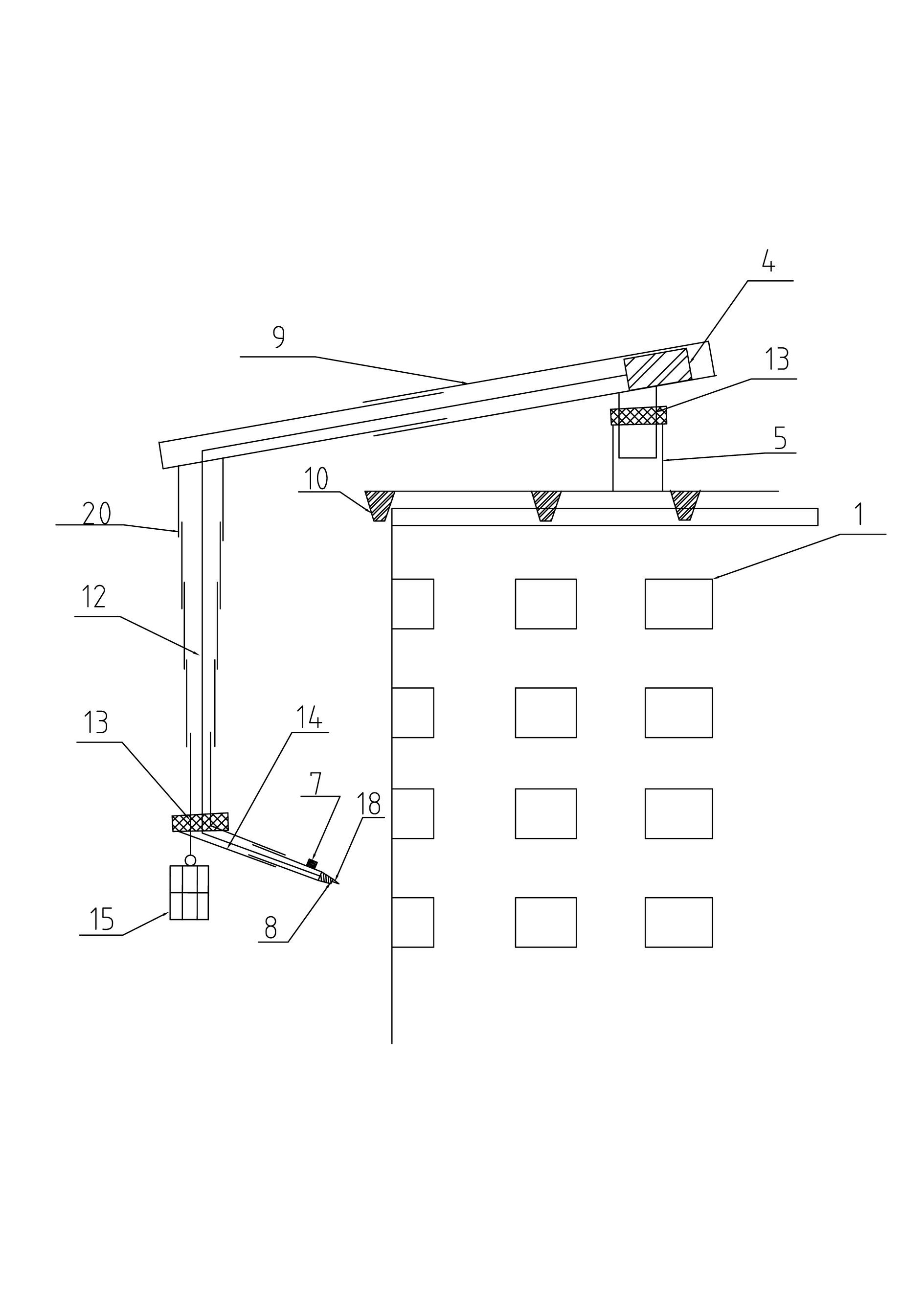
[0037] Such as Figure 4 As shown, a telescopic base 5 is provided on the top of the building 1, and the upper telescopic arm 9 is inclined downward and connected with the telescopic base 5, and stretches horizontally along the building 1, and the connection between the upper telescopic arm 9 and the telescopic base 5 There is a turning mechanism 13 that can make the upper telescopic arm 9 rotate around the telescopic base 5 . The steel wire rope 11 is connected with the multi-section telescopic arm or crank arm 14 that can be controlled by the control line 12 and stretches longitudinally along the building 1, and the slewing mechanism 13 connected with the steel wire rope 11 is equipped with a device to prevent the steel wire rope 11 from being subjected to reaction force and can be adsorbed on The suction cup 22 of the building 1 outer wall.

[0038] Other devices are the same as those in Embodiment 2, and will not be repeated here.


PUM


Abstract

The invention relates to a fire extinguishing apparatus, in particular to a remote control type fire extinguishing apparatus for a high-rise building, which comprises a water tank arranged at the top of the building, and also comprises a fire extinguishing mechanism sliding to the side surface of the building from the top of the building through a connecting mechanism, and a nozzle arranged outside the building and rotatably communicated to the water tank. The fire extinguishing mechanism comprises a connecting arm capable of controlling the action through a control line, and the bottom end of the connecting arm is provided with a nozzle communicated to the water tank and the side surface of the connecting arm is provided with a camera, the contact part of the connecting arm and the connecting mechanism is provided with a rotating mechanism capable of enabling the connecting arm to rotate, the control line of the connecting arm and the connecting mechanism are connected to a winch mechanism which is arranged at the top of the building and is capable of being remotely controlled, and the flexibility of the control line of the connecting arm and the connecting mechanism is controlled by the winch mechanism. The fire extinguishing apparatus can be used for immediately controlling the fire spread and eliminating fire at a fire point of the high-rise building.

Description

technical field [0001] The invention relates to a fire extinguishing device, in particular to a remote high-rise building fire extinguishing device. Background technique [0002] At present, the traditional fire extinguishing method is used in high-rise buildings: firefighters use the fire-fighting ladder truck to ascend the fire-extinguishing device from the bottom of the high-rise building to carry out fire-fighting work. For heights that cannot be reached by fire-fighting ladders and water hoses, firefighters need to enter the fire site and lay fire-fighting hoses by themselves. Extinguishing. However, this fire extinguishing method has the following limitations: [0003] (1) The best rescue time for firefighting in high-rise buildings is at the initial stage of fire. After a high-rise building catches fire, the fire spreads quickly. If the fire can be effectively controlled in the early stage of fire, the loss can be minimized. However, firefighters generally cannot Ju...

Claims


Application Information

Patent Timeline
Patent Type & Authority Applications(China)
IPC IPC(8): A62C3/00
Inventor 范伟林
Owner 范伟林
Why Eureka
Try Eureka