
Driving device

A driving device and driven technology, applied in valve devices, engine components, machines/engines, etc., can solve the problem of ineffective control of engine intake and exhaust and combustion conditions, and inability to control the opening and closing phases of intake and exhaust valves and lift. , engine and lift characteristic curves are invariable, etc., to reduce assembly costs, improve reliability and stability, and reduce development costs.

Inactive Publication Date: 2011-06-22
杨鲁川
View PDF7 Cites 0 Cited by
  • Summary
  • Abstract
  • Description
  • Claims
  • Application Information

AI Technical Summary

Problems solved by technology

[0003] The characteristic curve of the engine and the lift using this driving device is invariable, that is, the opening and closing phase and lift of the intake and exhaust valves cannot be controlled. Therefore, the intake, exhaust, and combustion conditions of the engine cannot be adjusted according to different working conditions. effective control

Method used


Image

  • Driving device
  • Driving device
  • Driving device

Examples


Embodiment Construction

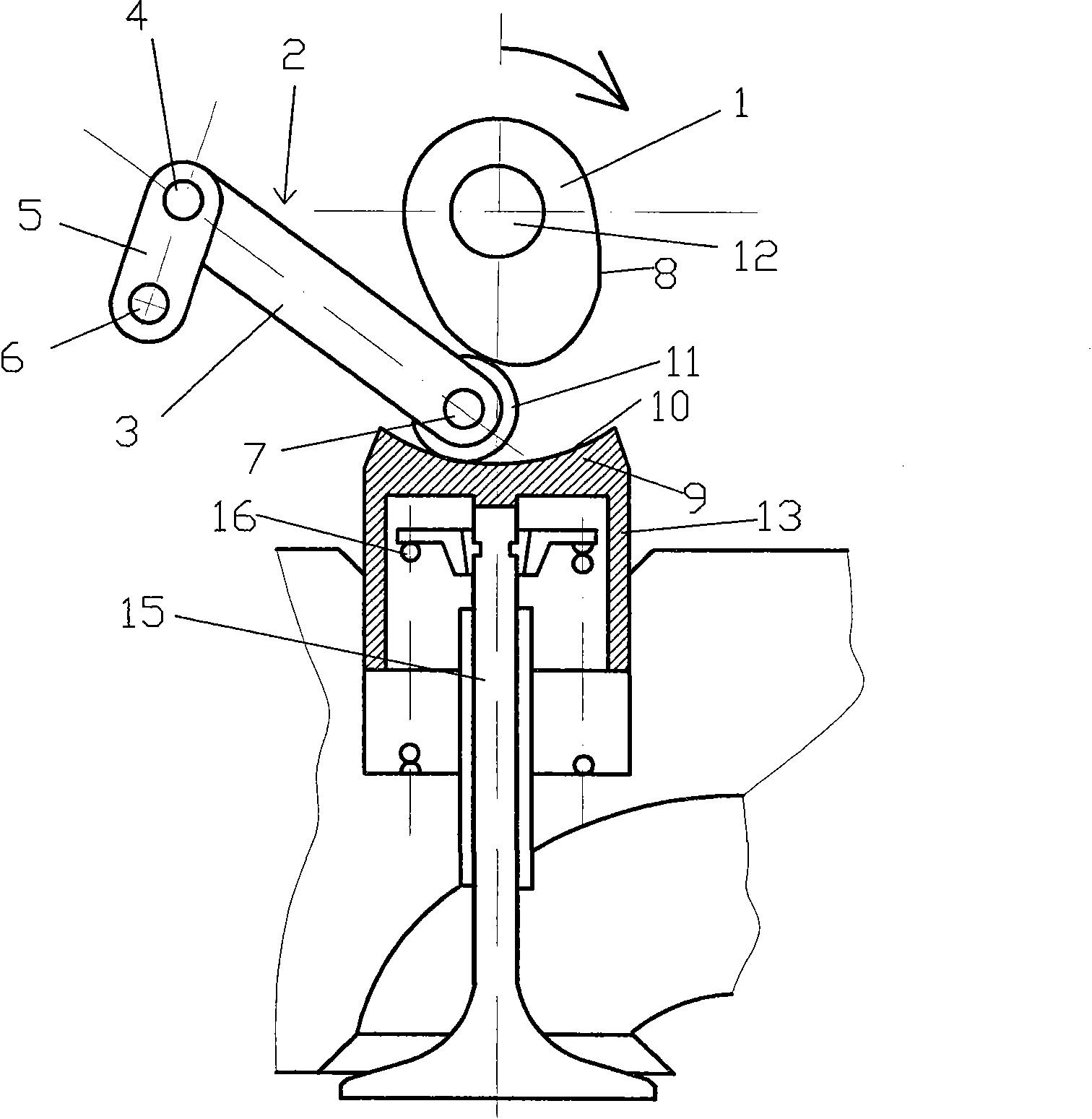
[0024] figure 1 A first embodiment of the drive device according to the invention is schematically represented. In this embodiment, the driving device drives the reciprocating motion of the engine cylinder valve stem.

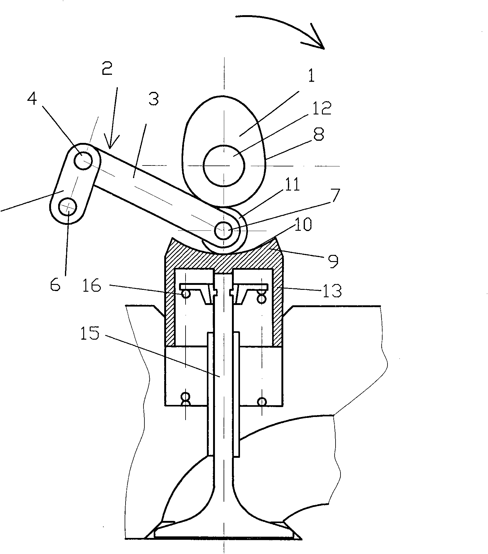
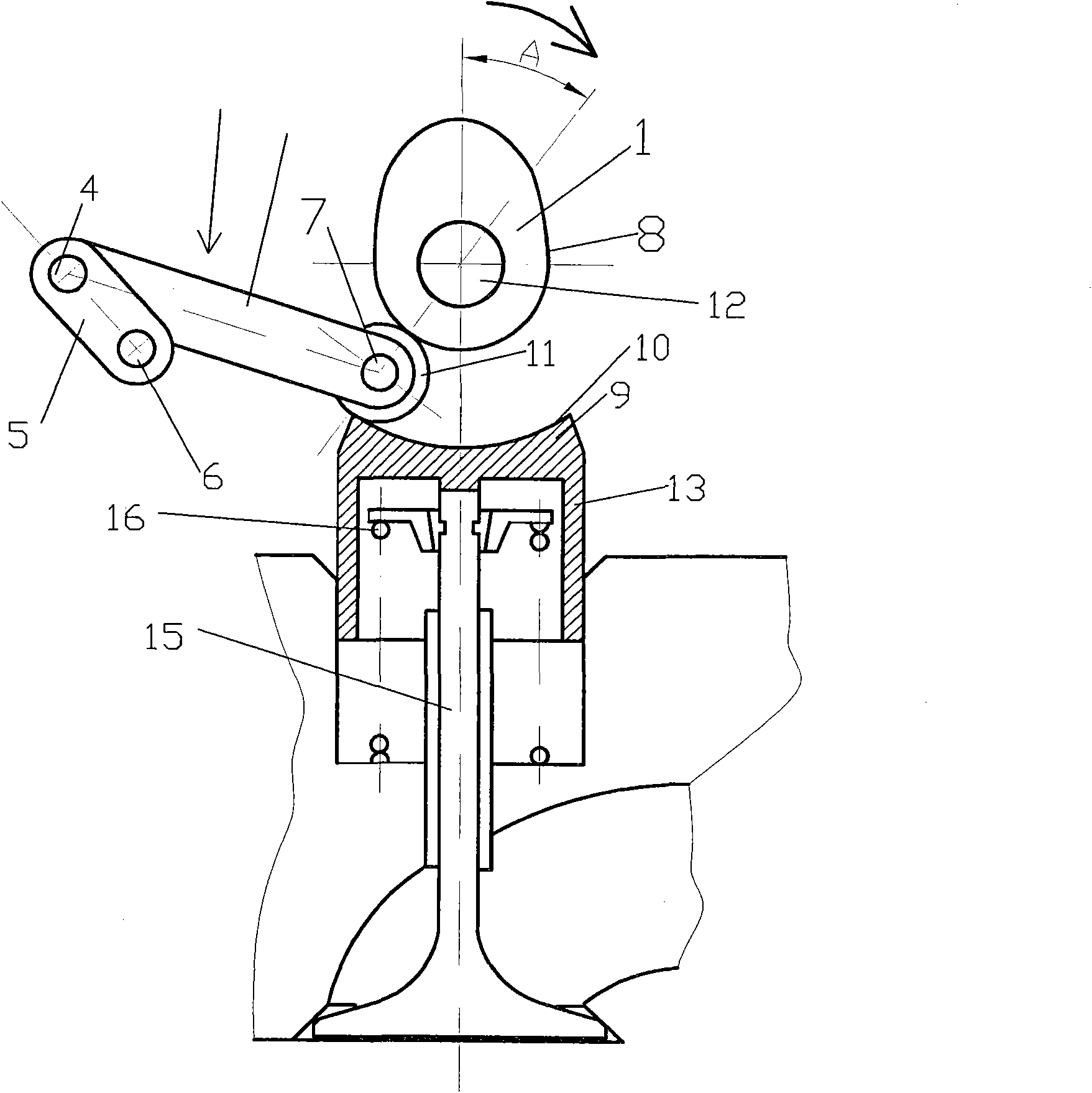
[0025] Such as figure 1 As shown, the driving device has a cam 1 and a transmission mechanism 2 . The cam 1 is mounted on a camshaft 12 . The camshaft 12 is powered by a power unit not shown in the figure, thereby driving the cam 1 to rotate. The transmission mechanism 2 includes a connecting rod 3, a crank 5, a guide 9 and a roller 11, the connecting rod 3 and the crank 5 are rotatably connected by a pin 4, the crank 5 is hingedly supported on the drive shaft 6, and the guide 9 is located on the upper part of the tappet 13 and integrally formed with the cylinder valve tappet 13, its top surface has an arc surface 10, and the roller 11 is hingedly connected to the end of the connecting rod 3 close to the cam 1 and the guide 9 through the pin 7 , the roller...


PUM


Abstract

The invention provides a driving device, which comprises a cam (1) and a transmission mechanism (2). The transmission mechanism (2) comprises a connecting rod (3), a crank (5), a guide piece (9) and a roller (11); the connecting rod (3) is rotationally connected with the crank (5) through a pin shaft (4); the crank (5) is hinged and supported on a driving shaft (6); the guide piece (9) is positioned on the upper part of a tappet (13) and integrally formed with the cylinder valve tappet (13), and the top surface of the guide piece is provided with a circular arc surface (10); the roller (11) is connected to the end of the connecting rod (3) close to the cam (1) and the guide piece (9) through a pin shaft (7); and the roller (11) is propped against the cam (1) and supported on the guide piece (9). By the rotation of the driving shaft (6), the contact position of the roller (11) and the cam (1) is regulated, so that the switching phase and the lift of an engine cylinder valve are regulated in real time, the combustion efficiency and the power of an engine are improved, and the energy consumption and the tail gas emission are reduced.

Description

technical field [0001] The invention relates to a driving device, in particular to a driving device for opening and closing engine intake and exhaust valves. Background technique [0002] In the prior art, there is a driving device in which a cam directly drives a driven part to perform reciprocating linear motion. For example, Japanese Patent Laying-Open No. 7-243310 discloses a drive device for the intake and exhaust valves of an engine, which directly drives the intake and exhaust valves to perform reciprocating linear motion by a cam. [0003] The characteristic curve of the engine and the lift using this driving device is invariable, that is, the opening and closing phase and lift of the intake and exhaust valves cannot be controlled. Therefore, the intake, exhaust, and combustion conditions of the engine cannot be adjusted according to different working conditions. effective control. Contents of the invention [0004] The object of the present invention is to provi...

Claims


Application Information

Patent Timeline
Patent Type & Authority Applications(China)
IPC IPC(8): F01L1/12
Inventor 杨鲁川
Owner 杨鲁川
Learn More