Differential gear for vehicle and vehicle

A differential device and vehicle technology, applied in the direction of differential transmission device, control device, transmission device, etc., can solve the problems such as the increase of the width of the shell and the restriction of the freedom of vehicle layout, so as to achieve the effect of ensuring rigidity

Inactive Publication Date: 2011-06-22
HONDA MOTOR CO LTD
View PDF8 Cites 1 Cited by
  • Summary
  • Abstract
  • Description
  • Claims
  • Application Information

AI Technical Summary

Problems solved by technology

[0007] However, in this structure, since it is necessary to form a cylindrical portion that sufficiently secures the movement stroke of the sleeve along the width direction of the housing (vehicle width direction), there is a possibility that the width dimension of the housing having a longer width dimension becomes further longer, The overall size of the differential device is large, which restricts the freedom of vehicle layout

Method used


Image

  • Differential gear for vehicle and vehicle
  • Differential gear for vehicle and vehicle
  • Differential gear for vehicle and vehicle

Examples


Embodiment Construction

[0063] Embodiments of the present invention will be described below with reference to the drawings.

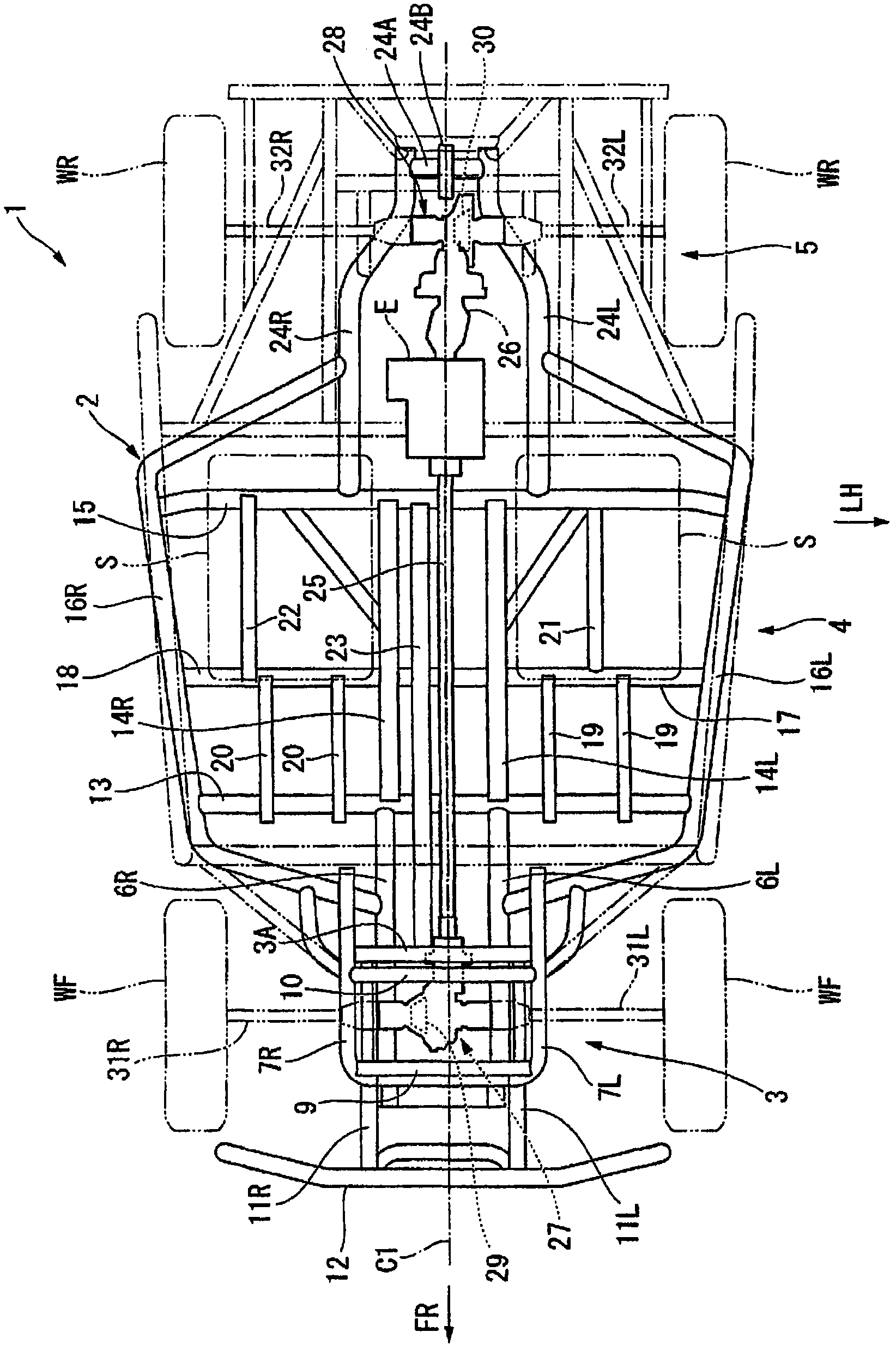
[0064] figure 1 It is a plan view showing a schematic configuration of a vehicle 1 having a differential device according to the present invention. In the drawings used for the following description, an arrow FR indicating the front of the vehicle and an arrow LH indicating the left of the vehicle are attached at appropriate positions, and these directions will be appropriately used hereinafter. In addition, C1 in the figure represents the center line of the vehicle 1 in the vehicle width direction.

[0065] The vehicle 1 is constituted as a relatively small vehicle (MUV) whose main purpose is to travel on uneven ground, and has a body frame 2 constituting the basic skeleton of the vehicle, and the body frame 2 includes a front frame portion 3 for suspending front wheels WF ; Be located at the rear of the front frame portion 3, and form the center frame portion 4 for disposi...


PUM


Abstract

A diff case (4) is attached to a side face of a ring gear wheel (48) on the opposite side to the side on which the ring gear wheel (48) and a pinion gear wheel (35) mesh with each other. The ring gear wheel (48) integrally has a boss portion (54), in which a driven shaft is fitted, on the meshing side with the pinion gear wheel (35). An annular member (56) slidably movable in an axial direction thereof is provided on the boss portion (54) with a guide portion for guiding the annular member (56). A lock pin (70) is provided on the annular member (56) for inserting into pin holes (71, 72) formed in the ring gear wheel (48) and a left output side cam to place the differential mechanism into a locked state. A sliding region within which the annular member (56) slidably moves is disposed so as to be included in a projection region of the diameter of the pinion gear wheel (35).

Description

technical field [0001] The present invention relates to a vehicle differential device having a mechanism for stopping a differential (differential lock, DIFF-LOCK), and a vehicle having the differential device. Background technique [0002] The differential gear is a device that absorbs the difference in rotation speed between the left and right drive wheels when the vehicle is turning, generates a rotation speed corresponding to each wheel, and distributes drive torque to each wheel. [0003] The differential device can be roughly divided into: a differential device with a general differential mechanism called an open differential (OPEN DIFF); a differential device with a so-called LSD (Limited Slip Differential; limited slip differential) ) The differential device of the differential speed limiting mechanism. Open differentials are often mounted on vehicles designed to drive on flat ground, and the differential speed limiting mechanism can limit the difference when one wh...

Claims


Application Information

Patent Timeline
Patent Type & Authority Applications(China)
IPC IPC(8): F16H48/00B60K17/16F16H48/08F16H48/20F16H48/24F16H48/30F16H48/38
CPCF16H48/14B60K17/346F16H48/24F16H2048/305F16H48/30
Inventor 佐藤浩二铃木荣一关文三
Owner HONDA MOTOR CO LTD
Why Eureka
Try Eureka