
Production equipment and production process for edge-turned flange of large pipe

A production process and pipe technology, which is applied in the field of large-scale pipe flanging flange production equipment and its production process, can solve the problems of desoldering, fluid leakage in the pipe, inconvenient transportation, etc., and achieve long service life, firm connection and simple structure Effect

Pending Publication Date: 2019-11-22
FUZHOU SENBAIDE ELECTROMECHANICAL TECH CO LTD
View PDF0 Cites 0 Cited by
  • Summary
  • Abstract
  • Description
  • Claims
  • Application Information

AI Technical Summary

Problems solved by technology

[0002] Large-scale pipes (large-scale fiber pipes) usually refer to fiber pipes with a diameter of more than 300 mm and a weight of more than a ton. These large-scale fiber pipes are made into round pipes during the production process. These pipes are usually used for large-scale water or oil pipelines. The use of roads, when used on site, these pipes need to be connected. The previous method is to carry out fusion welding. Fusion welding equipment is required for fusion welding. Usually the volume of fusion welding equipment is relatively large, and it can be used in relatively flat areas. Carrying equipment for transportation, but it is inconvenient to transport in hilly or mountainous areas. When used in these areas, manual welding is carried out gradually along the peripheral wall of the pipe. This method is not only inefficient, but also labor-intensive. Uneven heating of the welded pipes leads to desoldering, which can easily cause fluid leakage in the pipes

Method used


Image

  • Production equipment and production process for edge-turned flange of large pipe
  • Production equipment and production process for edge-turned flange of large pipe
  • Production equipment and production process for edge-turned flange of large pipe

Examples


Embodiment Construction

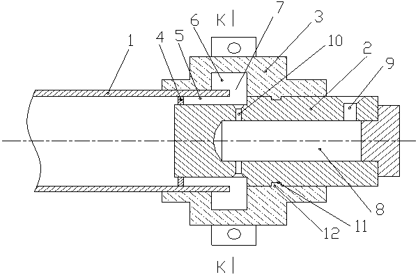
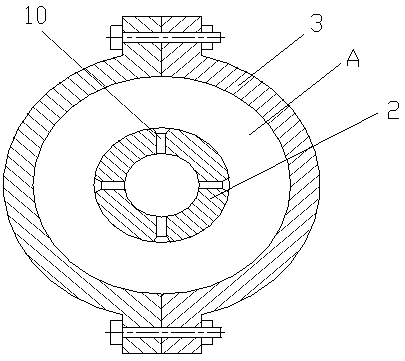
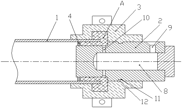
[0023] The large pipe flanging flange manufacturing equipment of the present invention comprises a large pipe 1, the large pipe 1 is a fiber pipe with a large diameter, and a stepped inner shaft 2 extending into the end body of the large pipe, and the stepped inner shaft 2 is divided into small pipe diameter sections and the large pipe diameter section, the outer mold sleeve 3 is clamped between the end of the large pipe material (the end is the position where the flanging flange is to be made) and the outer periphery of the inner shaft (located on the outer periphery of the large pipe diameter section). The die set 3 is composed of two halves, which are fixed by bolts. The first end of the inner shaft of the step (referring to the end facing the large pipe 1) is set with a limit ring for fixing in the end body of the large pipe. Ring 4, the limit ring 4 can be a metal ring, which needs to be fixed on the inner peripheral wall of the end of the large pipe 1 in the process of ma...


PUM

PropertyMeasurementUnit
Taperaaaaaaaaaa

Abstract

The invention provides production equipment and a production process for an edge-turned flange of a large pipe. The production equipment for the edge-turned flange of the large pipe is characterized by comprising the large pipe, a stepped inner shaft stretching into an end part body of the large pipe, and an outer die sleeve clamped at the end part of the large pipe and the periphery of the innershaft, wherein a limit ring used for being fixed into the end part body of the large pipe is arranged on a first end part of the stepped inner shaft in a sleeved manner; the shaft diameter of the first end part of the stepped inner shaft is less than the shaft diameter of an inner pipe wall of the large pipe, so that an annular gap ring is formed; a groove is formed in the inner wall surface of the outer die sleeve; the groove and the annular gap ring form a pouring cavity body used for producing the edge-turned flange; a central pouring flow channel, as well as a pouring-in port and a pouring-out port which communicate with the central pouring flow channel are formed in the stepped inner shaft; and the pouring-out port faces the pouring cavity body. The production equipment for the edge-turned flange of the large pipe is beneficial to facilitating to production for the flange on the end part of the large pipe, and facilitates to the subsequent installation.

Description

Technical field: [0001] The invention relates to a large pipe flanging flange manufacturing equipment and a manufacturing process thereof. Background technique: [0002] Large-scale pipes (large-scale fiber pipes) usually refer to fiber pipes with a diameter of more than 300 mm and a weight of more than a ton. These large-scale fiber pipes are made into round pipes during the production process. These pipes are usually used for large-scale water or oil pipelines. The use of roads, when used on site, these pipes need to be connected. The previous method is to carry out fusion welding. Fusion welding equipment is required for fusion welding. Usually the volume of fusion welding equipment is relatively large, and it can be used in relatively flat areas. Carrying equipment for transportation, but it is inconvenient to transport in hilly or mountainous areas. When used in these areas, manual welding is carried out gradually along the peripheral wall of the pipe. This method is no...

Claims


Application Information

Patent Timeline
IPC IPC(8): B29C69/00B29C39/10B29C39/26
CPCB29C69/00B29C39/10B29C39/26
Inventor 王强
Owner FUZHOU SENBAIDE ELECTROMECHANICAL TECH CO LTD
Learn More