Processing box
A technology for processing cartridges and developing rollers, applied in electrography, optics, instruments, etc., can solve problems such as drifting out, or transferring to non-printing areas, not being transferred to photosensitive drums, and affecting printing effects, etc. Achieve the effect of avoiding quality defects, good printing effect and cost saving
- Summary
- Abstract
- Description
- Claims
- Application Information
AI Technical Summary
Problems solved by technology
Method used
Image

Examples
Embodiment 1
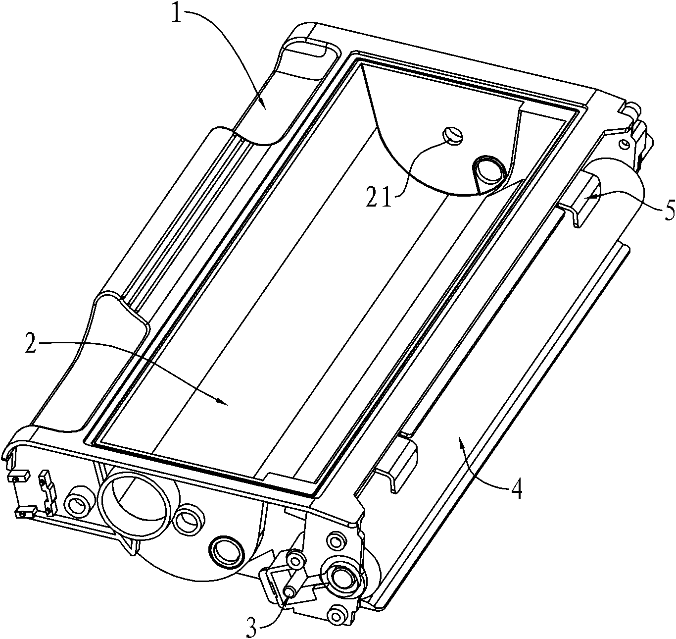
[0039] Such as image 3 As shown, the developing assembly of the process cartridge in this embodiment. On the frame 1 of the developing assembly, there is a powder bin 2 for storing carbon powder. In the powder bin 2, there is a shaft hole 21 for rotatably installing the stirring frame. The stirring frame is not shown in the figure, and the powder bin 2 is opened on one side There is a rectangular opening 22, and the powder feeding roller 3 is located at the rectangular opening 22. When the stirring frame rotates, the toner in the powder bin 2 is thrown out and lands on the rotating powder feeding roller 3 of the rectangular opening 22 .
[0040] The developing roller 4 arranged parallel to the powder feeding roller 3 is rotatably installed on the frame 1. The distance between the powder feeding roller 3 and the developing roller 4 is very close. When there is carbon powder on the powder feeding roller 3, the rotating powder feeding roller 3 and the rotating ground The devel...
Embodiment 2
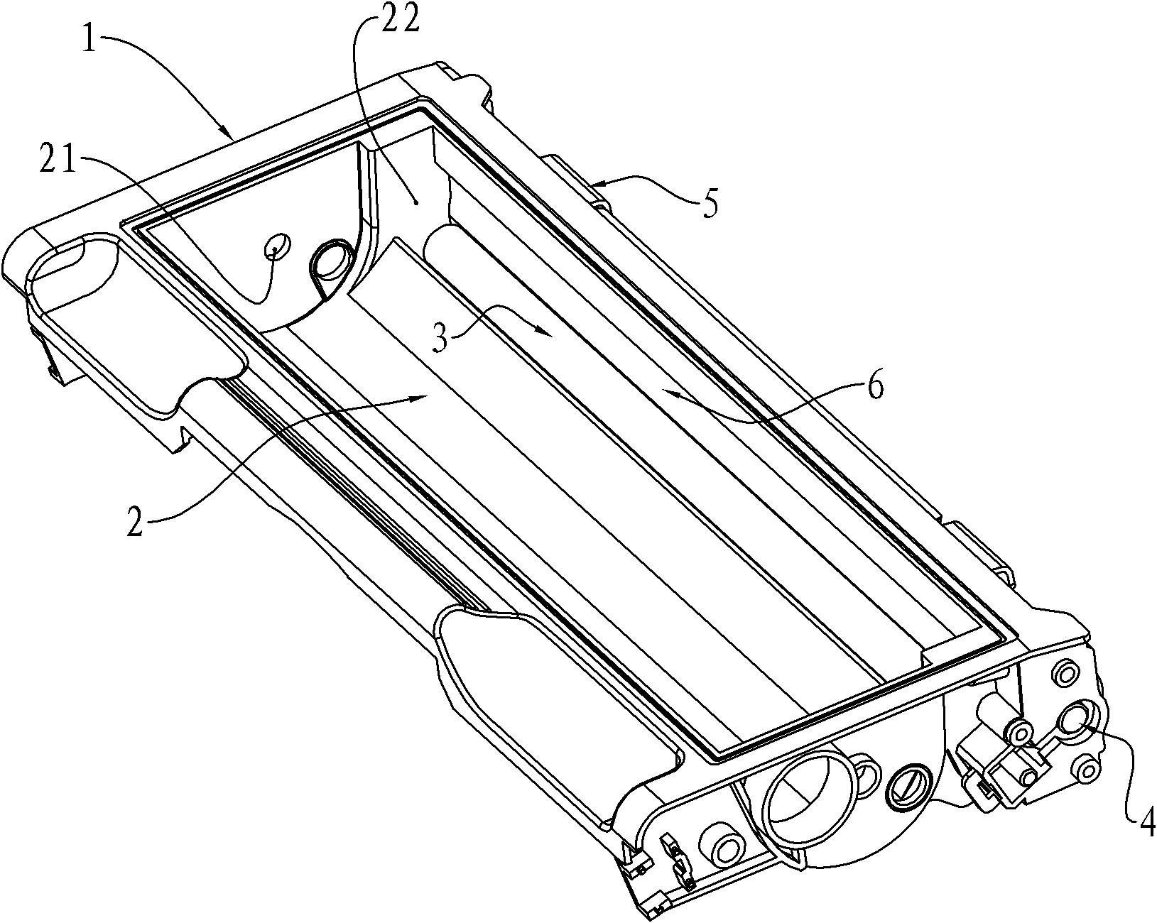
[0045] Such as Figure 6 As shown, the developing assembly of the process cartridge in this embodiment. On the frame 1 of the developing assembly, there is a powder bin 2 for storing carbon powder. In the powder bin 2, there is a shaft hole 21 for rotatably installing the stirring frame. The stirring frame is not shown in the figure, and the powder bin 2 is opened on one side There is a rectangular opening 22, and the powder feeding roller 3 is located at the rectangular opening 22. When the stirring frame rotates, the toner in the powder bin 2 is thrown out and lands on the rotating powder feeding roller 3 of the rectangular opening 22 .
[0046] The developing roller 4 which is close to the powder feeding roller 3 is rotatably installed on the frame 1. The distance between the powder feeding roller 3 and the developing roller 4 is very close. When there is carbon powder on the powder feeding roller 3, the rotating powder feeding roller 3 and the rotating ground The develop...
Embodiment 3
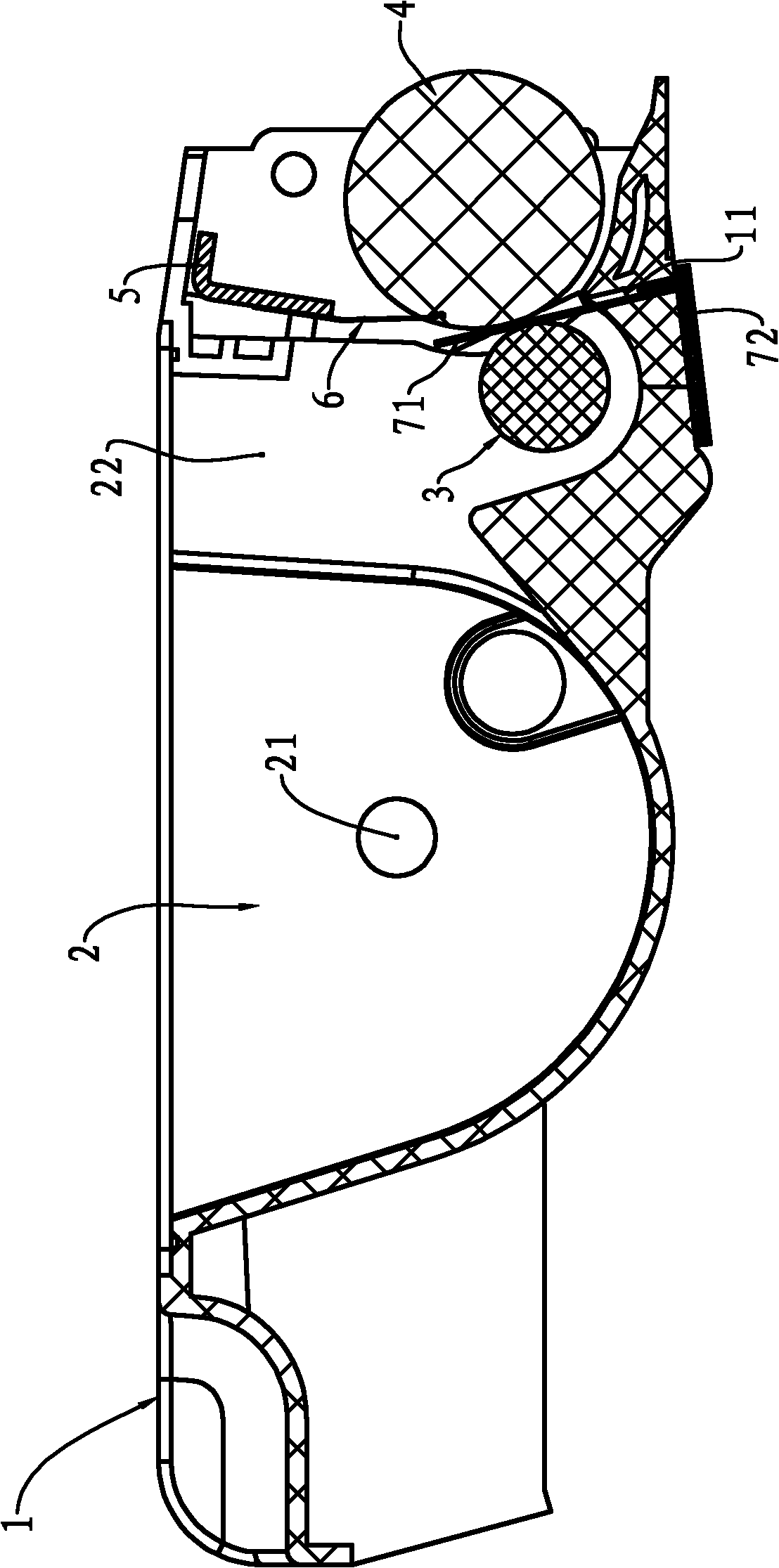
[0053] Such as Figure 8 , 9 Shown in and 10, the improvement of the process cartridge of the present embodiment lies in the powder outlet knife 6. The axial partition structure of the developing area is the structure at the edge of the powder outlet knife 6 . The blade of the powder outlet knife 6 is close to the axial ends of the developing roller, which is just a short extension 62 that is tangent to the surface of the developing roller, and the middle section of the blade of the powder outlet knife 6 is connected to a raised tail at the point of tangency. Long extension 61.
[0054] When the blade of the powder outlet knife 6 is just tangent to the upper surface of the developing roller 4, the powder outlet knife 6 scrapes off the carbon powder on the surface of the developing roller 4, so the carbon powder on the developing roller 4 corresponding to the short protruding section 62 When the blade of the powder outlet knife 6 has a tail that exceeds the tangent point, wh...
PUM
 Abstract
Description
Claims
Application Information
 - R&D
- Intellectual Property
- Life Sciences
- Materials
- Tech Scout
- Unparalleled Data Quality
- Higher Quality Content
- 60% Fewer Hallucinations
Browse by: Latest US Patents, China's latest patents, Technical Efficacy Thesaurus, Application Domain, Technology Topic, Popular Technical Reports.
© 2025 PatSnap. All rights reserved.Legal|Privacy policy|Modern Slavery Act Transparency Statement|Sitemap|About US| Contact US: help@patsnap.com