Cam for driving knitting needle and weft knitting machine

A flat knitting machine and triangular technology, applied in the direction of weft knitting, knitting, textile and paper making, etc., to achieve the effect of full contact depth and ensure contact depth

Active Publication Date: 2012-06-27
SHIMA SEIKI MFG LTD
View PDF2 Cites 0 Cited by
  • Summary
  • Abstract
  • Description
  • Claims
  • Application Information

AI Technical Summary

Problems solved by technology

[0005] In addition, each needle bed 15 is inclined so that the side of the needle bed 19 is higher and the side away from the needle bed 19 is lower, but for convenience of description, only one needle bed 15 is shown in a horizontal posture.

Method used


Image

  • Cam for driving knitting needle and weft knitting machine
  • Cam for driving knitting needle and weft knitting machine
  • Cam for driving knitting needle and weft knitting machine

Examples


Embodiment Construction

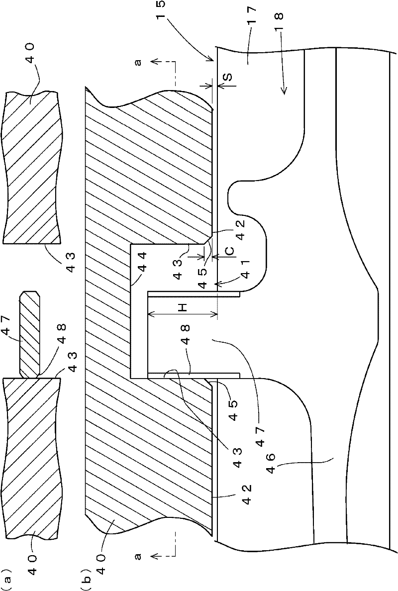
[0063] figure 1 (a) and figure 1 (b) shows the main part of the triangular member 40 which becomes one Embodiment of this invention as a simplified cross-sectional structure. in particular figure 1 (a) means from figure 1 (b) The section seen from section line a-a. In addition, in the following description, the part corresponding to the part demonstrated previously is denoted by the same reference symbol, and the overlapping description may be abbreviate|omitted.

[0064] triangle member 40, for example with the Figure 7 The movable needle raising cam 23 used in the cam system 20 has the grooved cam 37 as well as the grooved cam 41 . The cam member 40 is substantially plate-shaped, and is mounted on a bottom plate on the bottom side of the carriage of the flat knitting machine. The cam surface 42 of the cam member 40 faces the surface of the needle bed 15 with a gap S when the cam member 40 is mounted on the carriage. The gap S is, for example, 0.2 mm. The groove ...


PUM


Abstract

Provided is a cam for driving a knitting needle which can prevent seizure of the knitting needle to a butt, and also provided is a weft knitting machine. A cam member (40) for driving a knitting needle is mounted on a substantially planar carriage reciprocating along the surface of a needle bed (15). A grooved cam (41), having a cam wall face (43) which abuts on and guides a butt (48) projecting from a knitting member (46) contained in the needle groove (18) of the needle bed (15), to the outside of the needle grove (18), is formed in the cam member (40) to face the surface of the needle bed (15). The grooved cam (41) is provided with a chamfer (45), and the edge of the cam wall face (43) on the side of the cam surface (42) is removed. A butt (47) projects from the surface of the needle bed (15) by 2 mm or more. A clearance (S) of 0.2 mm is provided between the surface of the needle bed (15) and the cam surface (42). The edge is removed by the chamfer (45) over a range of 0.2-0.4 mm in the thickness direction from the cam surface of the grooved cam (41).

Description

technical field [0001] The present invention relates to a knitting needle driving cam and a flat knitting machine which are mounted on a carriage traveling along a needle bed to guide and drive butts of knitting needles protruding from needle grooves of the needle bed. Background technique [0002] Conventionally, in a flatbed knitting machine, knitting needles are accommodated in needle grooves arranged in parallel on a needle bed, and hooks on the front end side of the knitting needles are moved forward and backward to crests formed on the end side of the needle bed to knit a knitted fabric. The driving of the knitting needles to advance and retreat is performed by mounting the knitting needle driving cam on the base plate on the bottom surface side of the carriage that reciprocates in the parallel arrangement direction of the needle grooves. The knitting needle driving cam is substantially plate-shaped, and the surface formed so as to cut substantially perpendicularly fro...

Claims


Application Information

Patent Timeline
Patent Type & Authority Patents(China)
IPC IPC(8): D04B15/36
CPCD04B15/362
Inventor 有北礼治
Owner SHIMA SEIKI MFG LTD
Why Eureka
Try Eureka