Soot blower

A technology of equipment and pipelines, which is applied in the direction of lighting and heating equipment, cleaning of non-rotating equipment, cleaning of heat transfer devices, etc., can solve problems such as personal injury, equipment consumption, damage to instruments and boilers, and achieve no hidden dangers of accidents. Reduction, easy replacement effect

Inactive Publication Date: 2011-06-22
格奥尔格・布鲁恩德曼
View PDF0 Cites 6 Cited by
  • Summary
  • Abstract
  • Description
  • Claims
  • Application Information

AI Technical Summary

Problems solved by technology

The known devices are therefore relatively complex and expensive and require a considerable maintenance outlay
In addition, in such known devices there is the danger that when the blowpipe drive fails, the sealing system, such as the steam cylinder, will suddenly be squeezed apart, which can lead to enormous damage to the equipment and the boiler and even in the In the worst case, there will be consequences for human injury

Method used


Image

  • Soot blower
  • Soot blower
  • Soot blower

Examples


Embodiment Construction

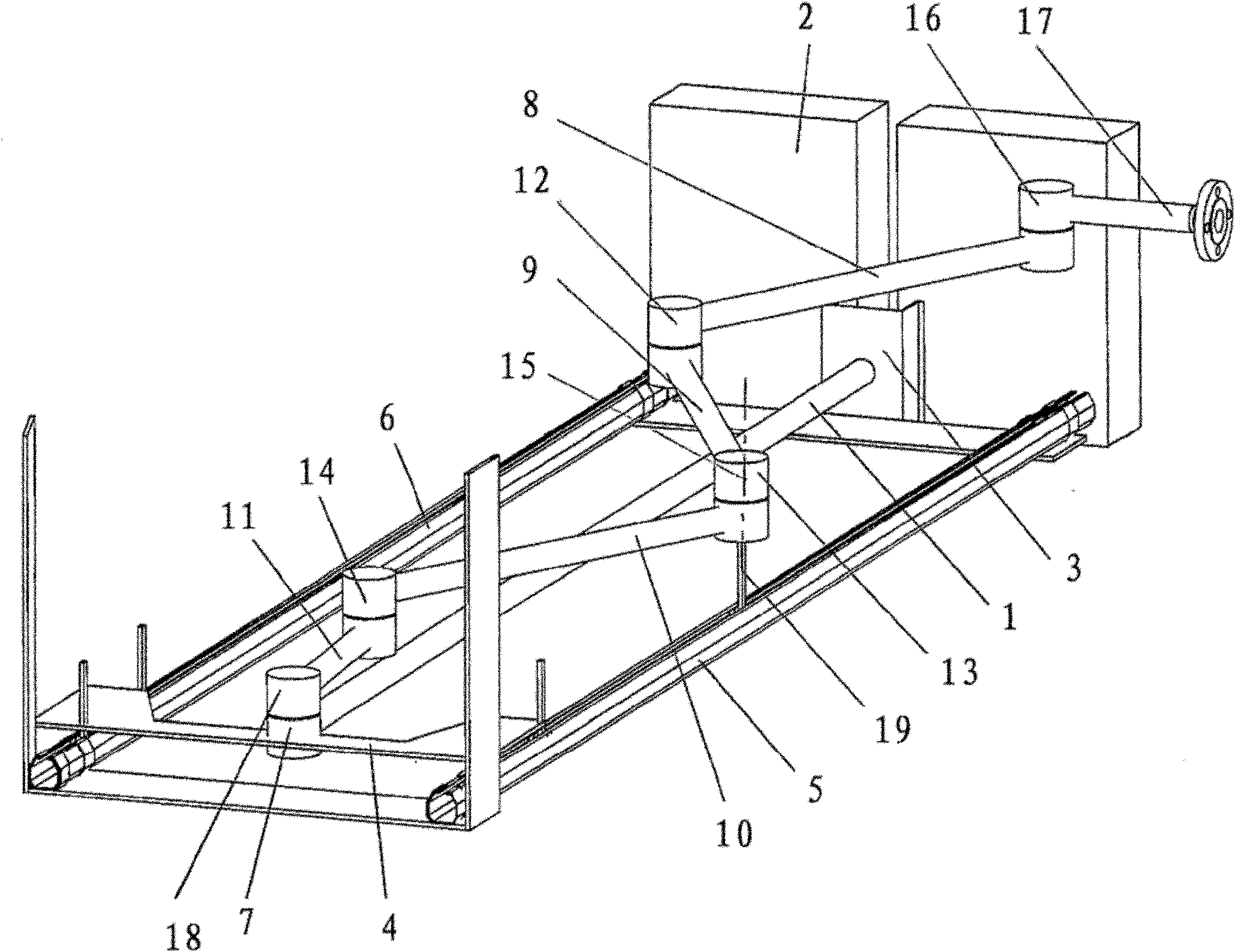
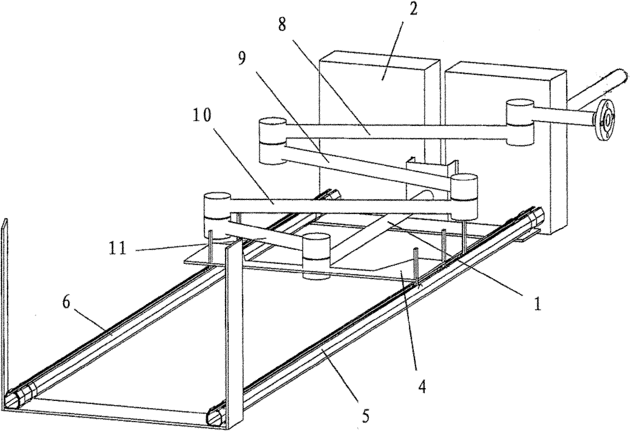
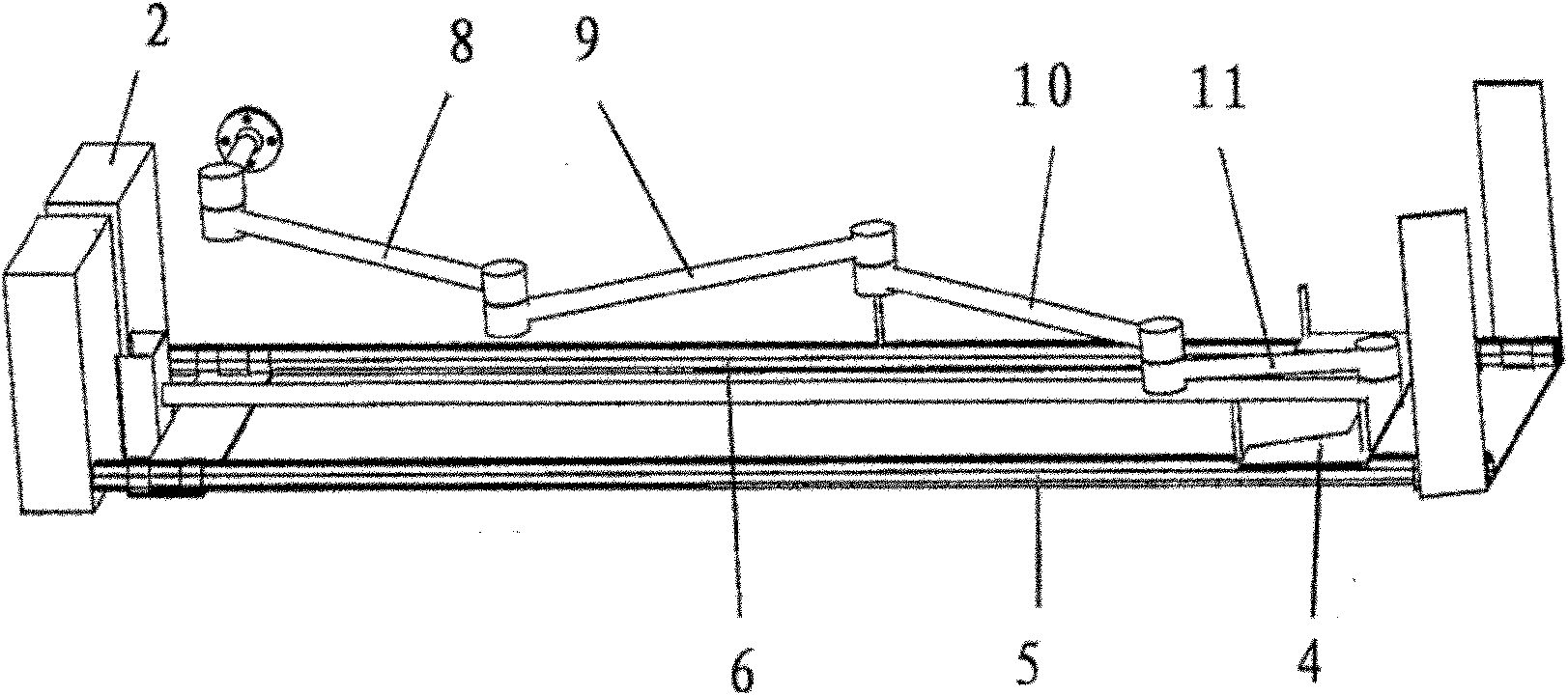
[0020] The sootblower shown in the drawing is used for cleaning the boiler while it is in operation and also for cleaning the heat transfer devices arranged in the boiler. The sootblower shown works with steam having a temperature of up to 420° C. and a pressure of 6 to 21 bar.

[0021] The soot blowing system essentially comprises an axially displaceable blowpipe 1 which can be moved into a schematically shown boiler 2 and out again after the cleaning process. On the boiler side, the lance 1 is guided in a support 3 . At the opposite end on the side facing away from the boiler 2 , the blowpipe 1 is fastened on a drivable, displaceable slide 4 . The blowpipe slide 4 is guided on two guide rails 5 , 6 extending parallel to the blowpipe 1 , with which the outer end 7 of the blowpipe 1 remote from the boiler 2 can be moved in the direction of the boiler 2 and away from it. .

[0022] Steam for cleaning is supplied to the outer end 7 of the blowpipe 1 via a plurality of pipe fi...


PUM


Abstract

The invention relates to a soot blower for cleaning boilers which are in operation, especially for cleaning heat transfer devices arranged in the boilers using a gaseous and / or liquid cleaning medium, such as vapor jets and / or water jets. The soot blower comprises a blow tube (1) which can be displaced in the axial direction and which comprises lateral outlet nozzles at the working end thereof. In order to create a simple and safe line feed to the blow tube (1), the feed line can be composed of at least two substantially straight, rigid line pipe pieces (8, 9, 10, 11), which are joined to each other by a line revolute joint (12, 13, 14) in each case. The line pipe piece (11) which forms the line end is joined to the inlet end (7) of the blow tube (1) by a line revolute joint (18), while the line pipe piece (8) which forms the line start is joined to the connecting piece (17) of the stationary line system of the cleaning medium by a line revolute joint (16). The rotational axes of all line revolute joints are arranged parallel to each other and substantially vertically.

Description

technical field [0001] The invention relates to a sootblower for cleaning a boiler in operation, in particular for cleaning a heat transfer device arranged in the boiler by means of a gaseous and / or liquid cleaning medium, such as steam and / or water jets, having An at least axially displaceable blowpipe with a lateral discharge nozzle at its working end, a drive system positionable outside the boiler for moving the blowpipe back and forth, and a supply of cleaning medium connected to the blowpipe pipeline. Background technique [0002] Large boilers must be cleaned during operation to avoid downtime. Here, cleaning is expediently performed with the aid of steam or water jets. Steam or water is introduced via a blowpipe into the boiler, where the medium exits through nozzles on the head side of the blowpipe, with the jet directed at the boiler part to be cleaned. [0003] In known installations, for example, work is carried out with steam at a temperature in excess of 400°...

Claims


Application Information

Patent Timeline
Patent Type & Authority Applications(China)
IPC IPC(8): F28G15/02F28G1/16F28G15/04
CPCF28G15/02F28G15/04F28G1/166
Inventor 格奥尔格·布鲁恩德曼
Owner 格奥尔格・布鲁恩德曼
Why Eureka
Try Eureka