

Forming equipment and forming method for macrofiber-reinforced thermoplastic resin
A technology for enhancing thermoplasticity and forming equipment, which is applied in the field of fully impregnating fibers with molten resin and forming equipment, and forming equipment for long fiber reinforced thermoplastic resins. It can solve the problem of reducing the infiltration effect of molten resin on circular bundle-shaped central fibers and affecting product quality Problems related to production efficiency, excessive temperature difference between fiber and resin, etc., achieve the effect of reducing material renewal speed, improving production efficiency, and reducing breakage
- Summary
- Abstract
- Description
- Claims
- Application Information
AI Technical Summary
Problems solved by technology
Method used
Image

Examples
Embodiment 1
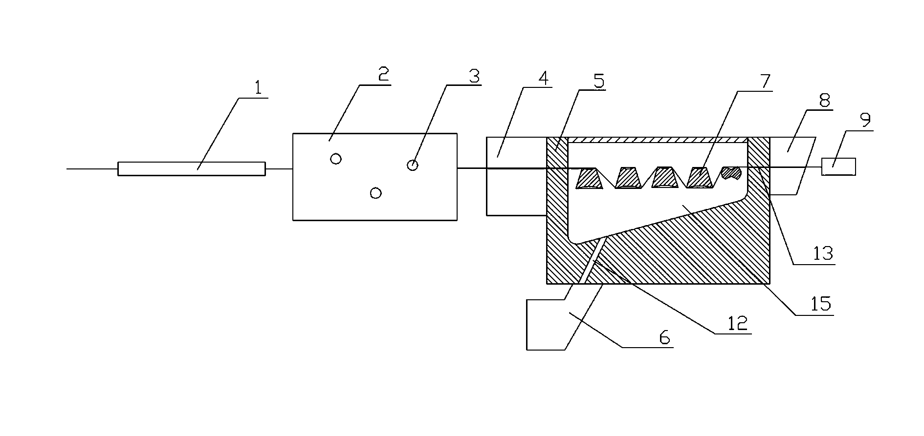
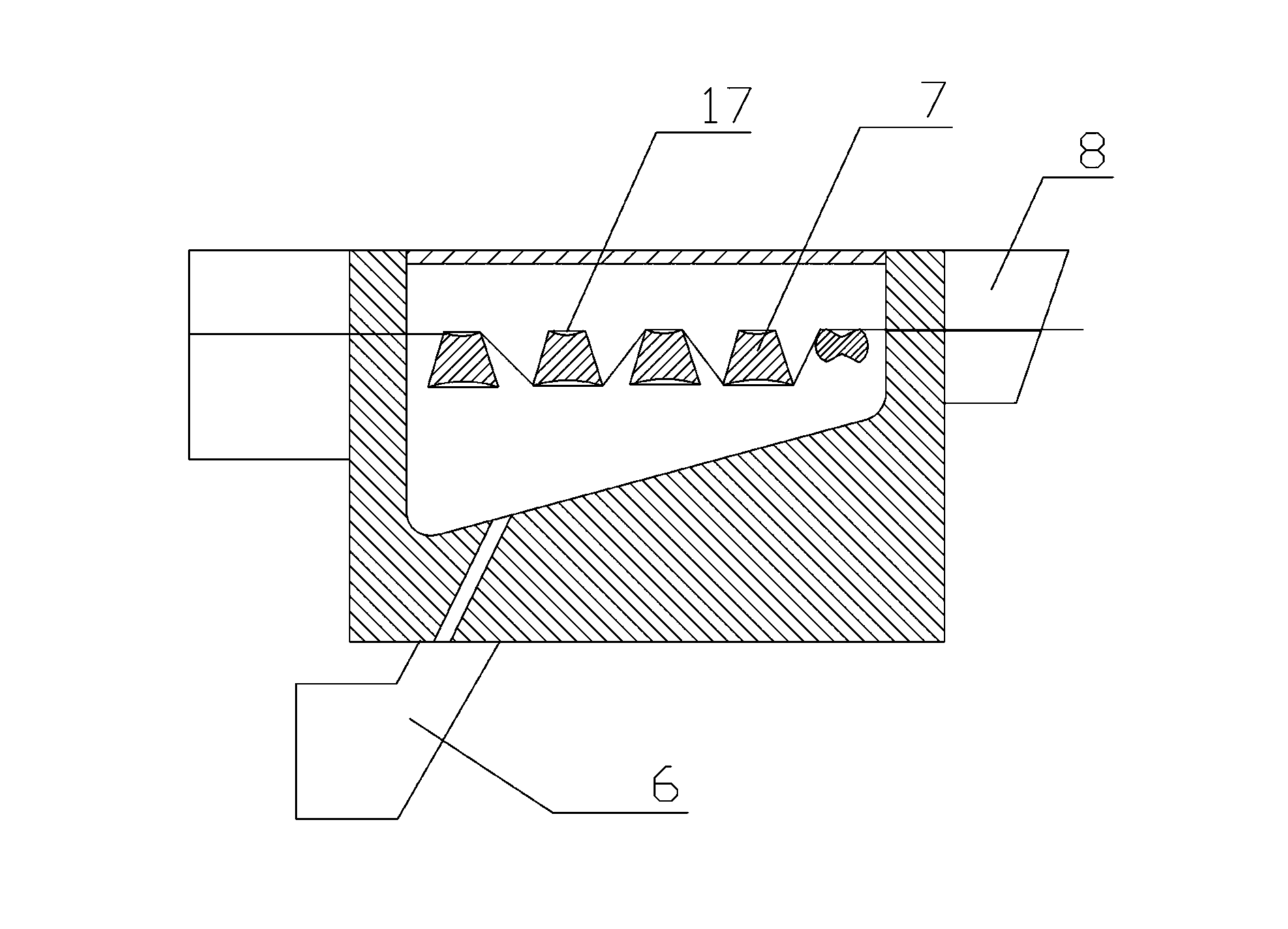
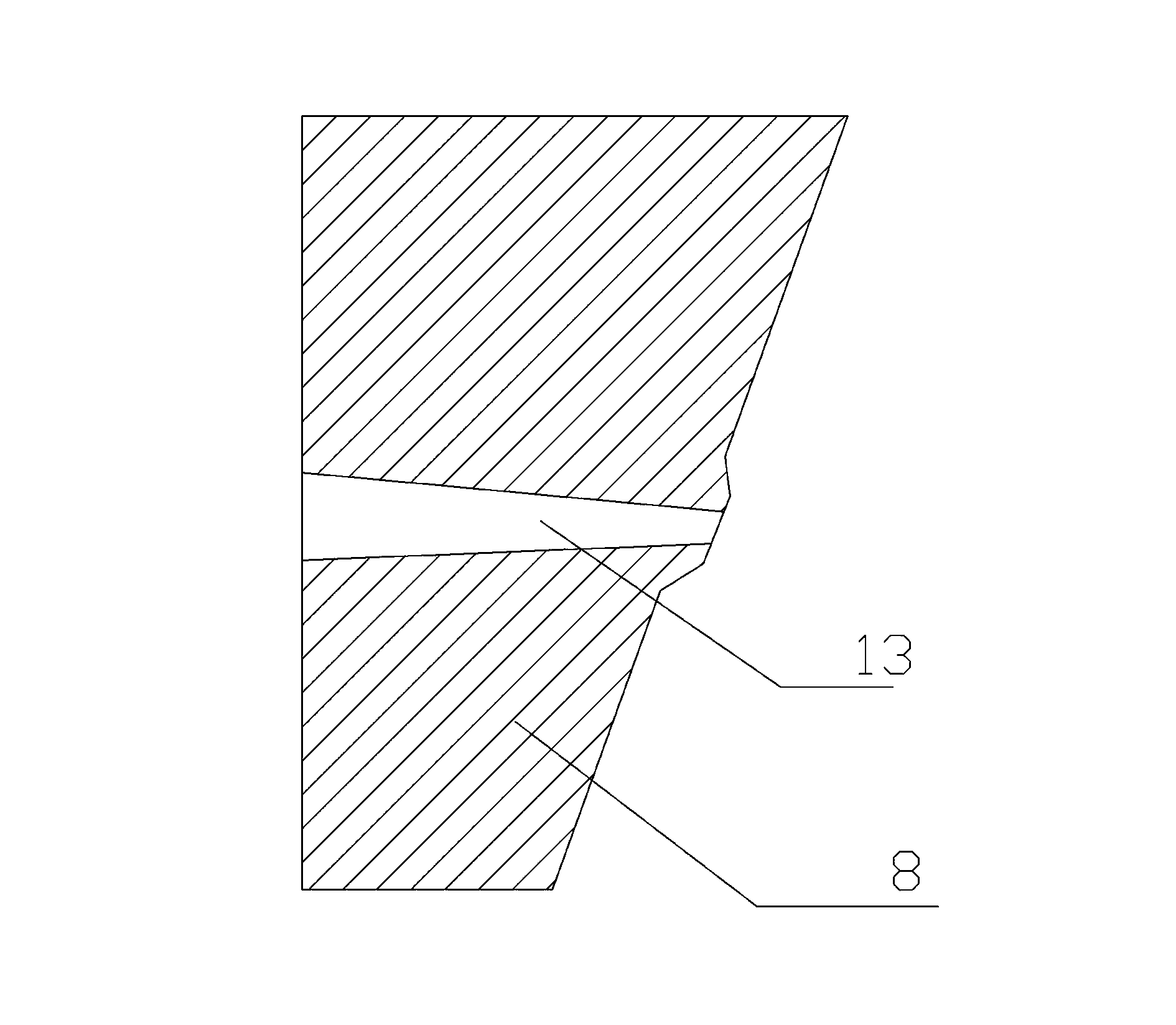
[0032] Such as Figure 1-3The melt impregnation method shown is the equipment for producing long-fiber reinforced thermoplastic resin, including the equipment for decomposing fiber loops into fiber bundles and pretreating them. The fiber bundle independent channel 1 is connected with the fiber pre-fluffing and preheating system 2; Full impregnation and molding equipment, its melt inlet die 6 communicates with the fiber impregnated body 5 through the melt inflow channel 12, and is inclined upward at a certain angle, and the fiber inlet die 4 is used to connect the fiber pre-fluffing and preheating system 2 and the fiber The impregnated body 5 can make the fiber enter the fiber impregnated body 5 horizontally, and the other end of the fiber impregnated body 5 is connected with the forming die 8 .
[0033] In addition, the melt inlet die 6, the fiber inlet die 4, the forming die 8 and the fiber impregnated body 5 are detachable and flexibly combined; the fiber bundle independent ...
Embodiment 2
[0039] Such as Figure 1-3 The melt impregnation method shown is the equipment for producing long-fiber reinforced thermoplastic resin, including the equipment for decomposing fiber loops into fiber bundles and pretreating them. The fiber bundle independent channel 1 is connected with the fiber pre-fluffing and preheating system 2; Full impregnation and molding equipment, its melt inlet die 6 communicates with the fiber impregnated body 5 through the melt inflow channel 12, and is inclined upward at a certain angle, and the fiber inlet die 4 is used to connect the fiber pre-fluffing and preheating system 2 and the fiber The impregnated body 5 can make the fiber enter the fiber impregnated body 5 horizontally, and the other end of the fiber impregnated body 5 is connected with the forming die 8 .
[0040] In addition, the melt inlet die 6, the fiber inlet die 4, the forming die 8 and the fiber impregnated body 5 are detachable and flexibly combined; the fiber bundle independent...
Embodiment 3
[0043] Such as Figure 1-3 The melt impregnation method shown is the equipment for producing long-fiber reinforced thermoplastic resin, including the equipment for decomposing fiber loops into fiber bundles and pretreating them. The fiber bundle independent channel 1 is connected with the fiber pre-fluffing and preheating system 2; Full impregnation and molding equipment, its melt inlet die 6 communicates with the fiber impregnated body 5 through the melt inflow channel 12, and is inclined upward at a certain angle, and the fiber inlet die 4 is used to connect the fiber pre-fluffing and preheating system 2 and the fiber The impregnated body 5 can make the fiber enter the fiber impregnated body 5 horizontally, and the other end of the fiber impregnated body 5 is connected with the forming die 8 .
[0044] In addition, the melt inlet die 6, the fiber inlet die 4, the forming die 8 and the fiber impregnated body 5 are detachable and flexibly combined; the fiber bundle independent...
PUM
 Abstract
Description
Claims
Application Information