Feeding template used for automatic cutting of material and control method thereof

A control method and material technology, which is applied in the field of rubber machinery, can solve problems such as prolonging the feeding cycle, material wrinkling, and front-end wear of the material, and achieve the effects of reducing the workload, maintaining quality, and shortening the feeding

Inactive Publication Date: 2011-06-29
MESNAC
View PDF10 Cites 6 Cited by
  • Summary
  • Abstract
  • Description
  • Claims
  • Application Information

AI Technical Summary

Problems solved by technology

[0003] Regardless of whether a mechanical cutter or a thermal hob is used for cutting, since the cutting surface of the material is relatively smooth and close to the side of the cutter body, friction between the cutter and the material during the retreat and reset process will easily cause the material to wrinkle Or deflection occurs, and it is easy to cause the front end of the material to be worn and affect the joint accuracy in the next laminating process
[0004] The existing common solution is to manually move the material back for a certain distance after cutting, which not only prolongs the feeding cycle and increases the workload of the operator, but also makes it difficult to evenly back and deliver the material from the bottom of the platen assembly. The material is easy to shift and directly affects the smooth implementation of the next process

Method used


Image

  • Feeding template used for automatic cutting of material and control method thereof
  • Feeding template used for automatic cutting of material and control method thereof
  • Feeding template used for automatic cutting of material and control method thereof

Examples


Embodiment 1

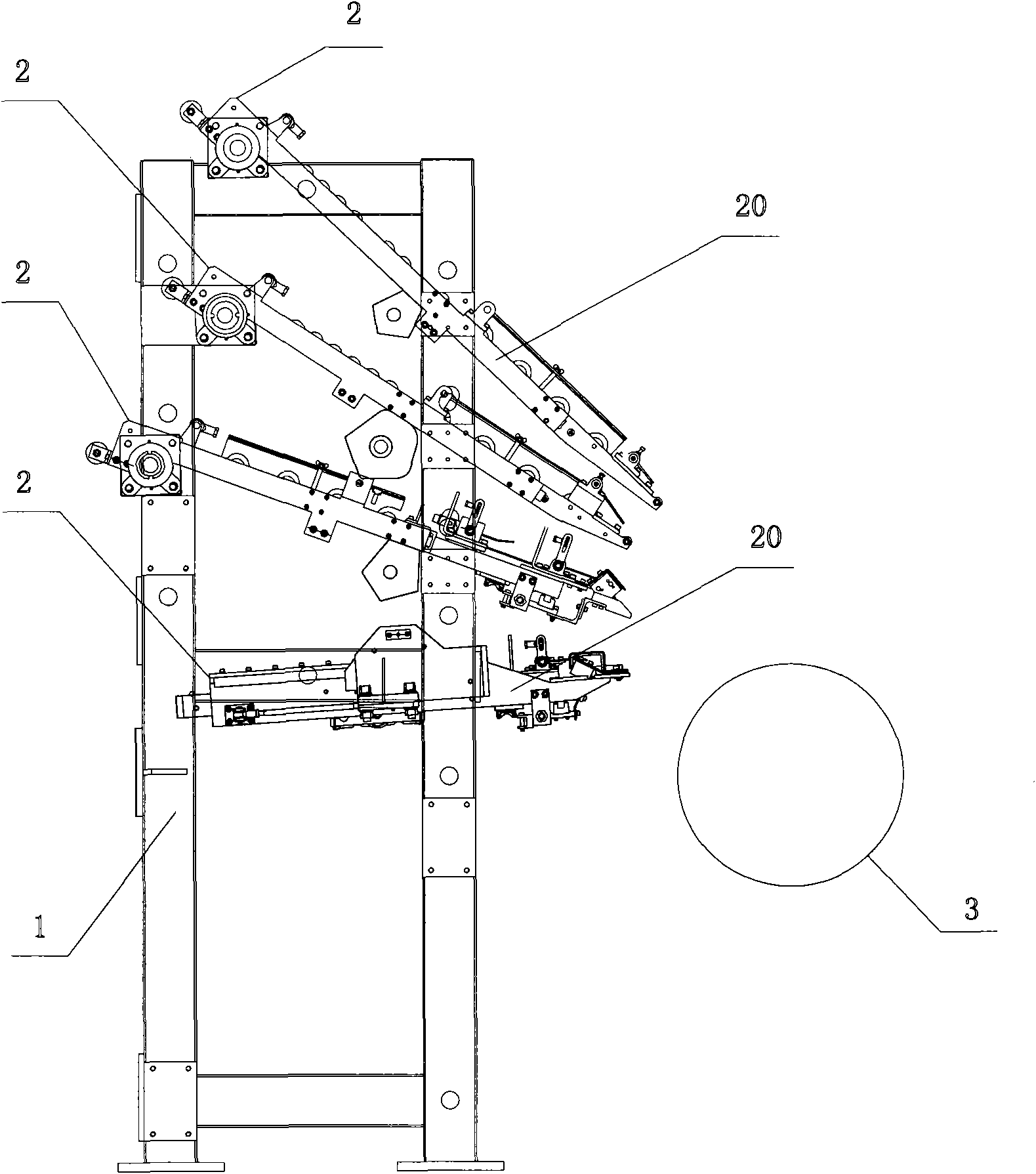
[0041] Example 1, in figure 1 In the application of the feeding device of the present invention, between the left and right wallboards 1, there are fixedly connected multiple sets of feeding templates 2 for conveying materials to the forming drum 3 to complete the material joint and lamination operation.

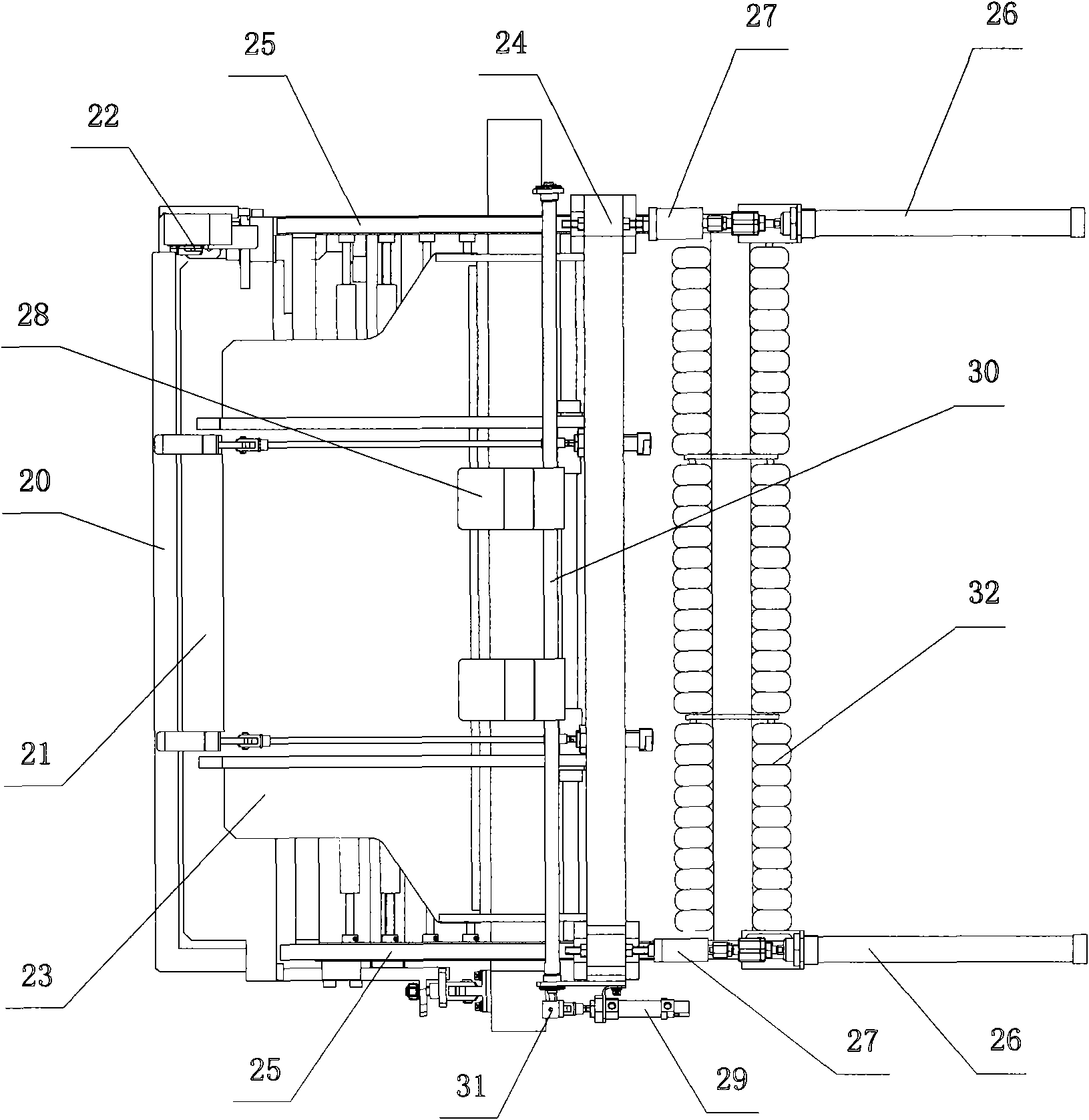
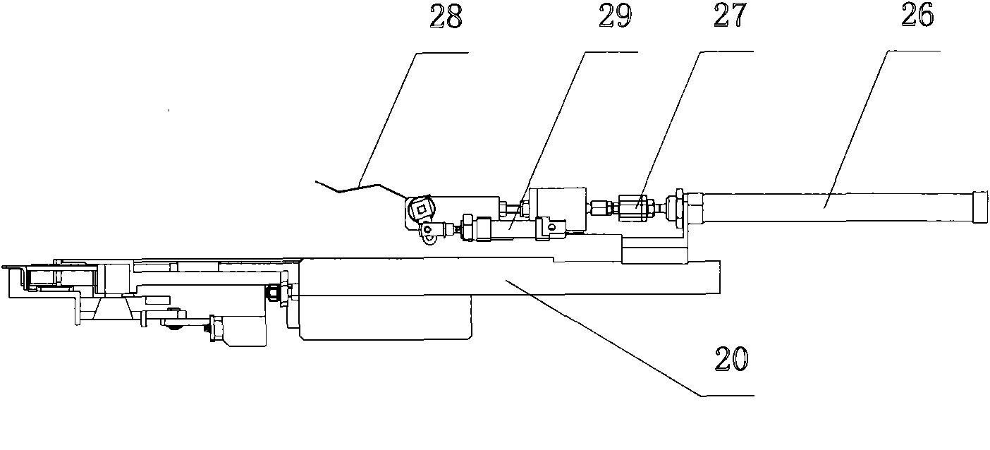
[0042] like figure 2 and image 3 As shown, the feeding templates for material conveying and automatic cutting mainly include:

[0043] a frame 20,

[0044] A plurality of groups of conveying rollers 30 for longitudinally conveying materials are arranged on the frame 20 .

[0045] A front end plate 21 and a cutting knife 22 for horizontally cutting materials are arranged at the front end of the frame 20 , and a longitudinal feeding device is arranged at the rear side of the front end plate 22 .

[0046] Wherein, the longitudinal feeding device has a feeding plate 23 that carries materials upwards and conveys materials to the forming drum 3 along the longitudinal directi...


PUM


Abstract

The invention relates to a feeding template used for the automatic cutting of material and a control method thereof, wherein, a material transmission device that can reciprocate in the longitudinal direction is adopted to control the material to be forwards conveyed accurately to reach a feeding station, and the material can move backwards for a certain distance so as to be detached from being in contact with a cutting knife when being processed through fixed-length cutting, so that the phenomenon that the material wrinkles or deflects caused by the backward reposition of the cutting knife is hindered, and the material can be protected from being abraded. The feeding template mianly comprises a frame, wherein, a front end plate and the cutting knife used for cutting the material transversely are arranged at the front end of the frame. A longitudinal material transmission device is arranged on the rear side of the front end plate; the longitudinal material transmission device is provided with a material transmission plate, at least a group of cylinder components, a pressure plate and a driving cylinder; the material transmission plate can bear upwards and can convey the material in the longitudinal direction; the cylinder components are connected with the rear end of the material transmission plate and can drive the material transmission plate to reciprocate in the longitudinal direction; the pressure plate is arranged above the material transmission plate; and the driving cylinder can drive the pressure plate to swing in the vertical direction. The material can move backwards for a certain distance so as to be detached from being in tight contact with the inner side surface of the cutting knife after being processed through fixed-length cutting.

Description

technical field [0001] The invention relates to a feeding template for material conveying and cutting and a control method thereof, belonging to the field of rubber machinery. Background technique [0002] At present, in the pre-sequence process of rubber tire manufacturing and processing, it is necessary to bond and roll the various parts that constitute the semi-finished tire on the forming drum, such as conveying the materials such as steel cord, inner liner or belt layer in sequence, Wrapped on the forming drum, and then cut to length to complete a laminating process. [0003] Regardless of whether a mechanical cutter or a thermal hob is used for cutting, since the cutting surface of the material is relatively smooth and close to the side of the cutter body, friction between the cutter and the material during the retreat and reset process will easily cause the material to wrinkle Or deflection occurs, and it is easy to cause the front end of the material to be worn and ...

Claims


Application Information

Patent Timeline
Patent Type & Authority Applications(China)
IPC IPC(8): B29D30/30
Inventor 曹大伟张殿勇程俊峰李海涛
Owner MESNAC
Why Eureka
Try Eureka