Motor vehicle collision device with jet energy consumer

A technology of collision device and energy dissipator, which is applied to bumpers and other directions, can solve problems such as extrusion deformation of motor vehicle body, unfavorable personnel protection, and reduction of piston cylinder length, so as to reduce rollover and tail swing accidents, and reduce injuries or deaths. , the effect of reducing the number of injection holes

Inactive Publication Date: 2011-06-29
凌建军
View PDF1 Cites 2 Cited by
  • Summary
  • Abstract
  • Description
  • Claims
  • Application Information

AI Technical Summary

Problems solved by technology

But this patent has the following problems: ①During the collision process, since the number of nozzles participating in the injection is constant, the test results show that the speed curve of the motor vehicle body is a half-width sinusoidal curve, and the piston advances about 2/3 of the distance and consumes 92% of the engine power. The kinetic energy of the motor vehicle, the remaining 1/3 of the distance only consumes 8% of the kinetic energy of the motor vehicle, which is manifested in the excessive peak pressure of the liquid in the tubular stringer and the peak acceleration of the vehicle body. The problem to be solved is to reduce the peak pressure and acceleration peak
This is because when a frontal collision occurs, the front piston has already extended into the bottom of the front piston cylinder. At this time, a rear-end collision occurs. When the rear piston is pushed forward, the front piston will also move forward at the same time, and the reset process of the front piston will consume almost no energy. Any energy, the pressure of the liquid in the tubular stringer cannot be established, and the nozzle type energy consumption device and the piston type energy consumption device cannot function at this time. crush casualty
③When the motor vehicle collides at a very high speed, the propulsion distance of...

Method used


Image

  • Motor vehicle collision device with jet energy consumer
  • Motor vehicle collision device with jet energy consumer
  • Motor vehicle collision device with jet energy consumer

Examples


no. 1 approach

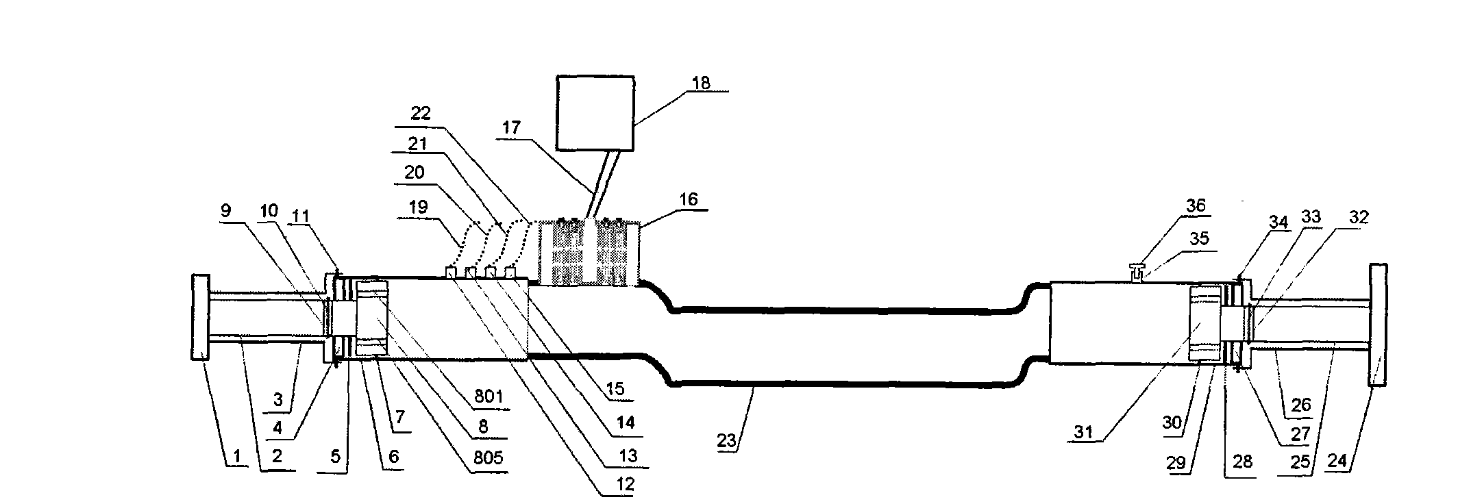
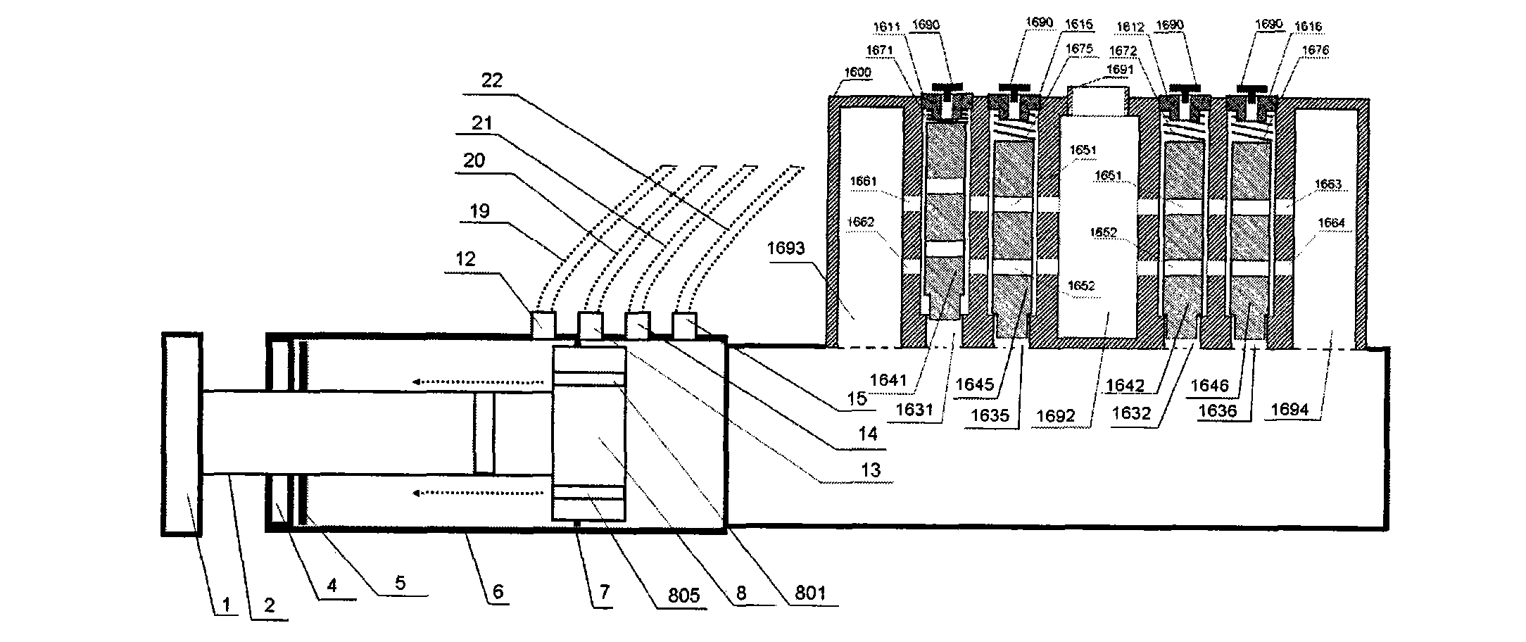
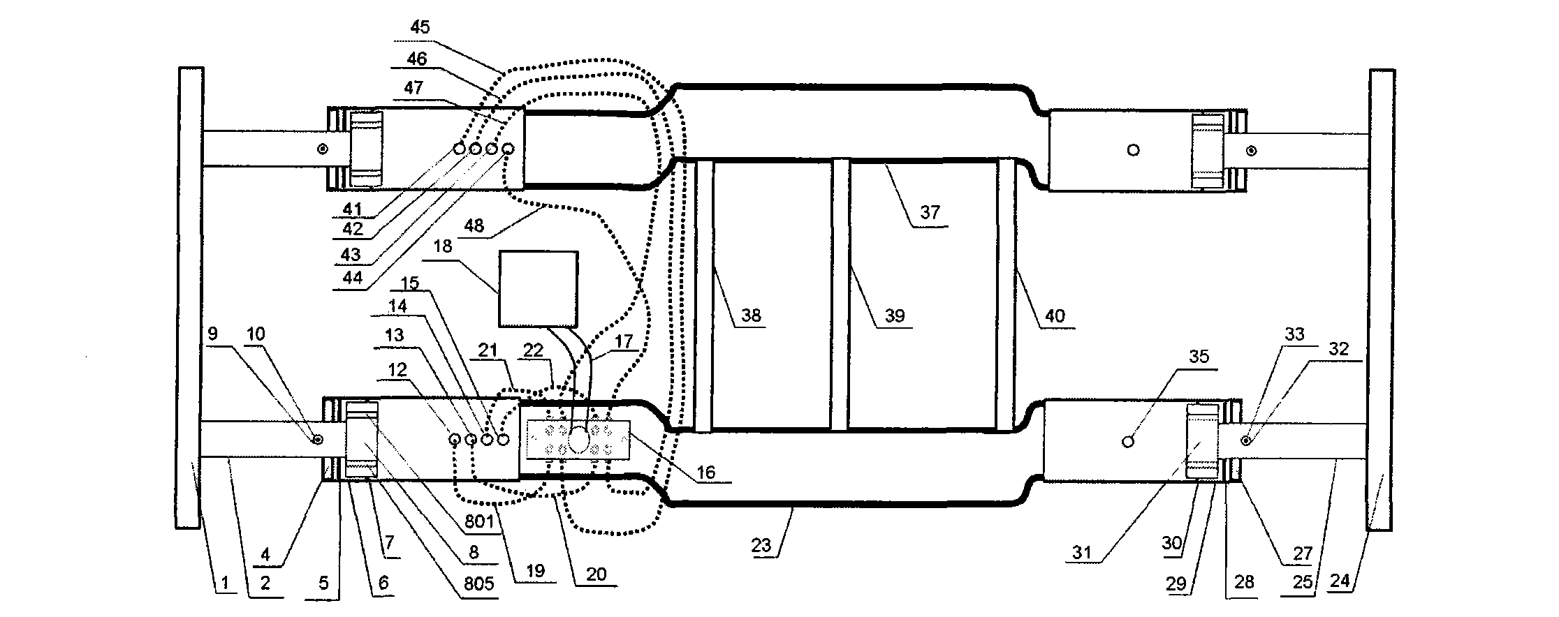
[0049] Such as Figure 1 to Figure 15As shown, the motor vehicle collision device with jet energy consumption device of the present invention comprises a first collision rod 1, a first piston push rod 2, a first preload sleeve 3, a first piston cylinder end cover 4, a first piston injection Hole seal washer 5, first piston cylinder 6, first piston seal ring 7, first piston 8, first pin hole 9, first pin 10, first fixing screw 11, first screw joint 12, second screw Hole joint 13, third screw joint 14, fourth screw joint 15, jet energy consumer 16, low pressure connecting pipe 17, antifreeze buffer box 18, first tubular longitudinal beam 23, second collision bar 24, The second piston push rod 25, the second pre-tensioning sleeve 26, the second piston cylinder end cover 27, the second piston injection hole sealing gasket 28, the second piston cylinder 29, the second piston sealing ring 30, the second piston 31, The second pin hole 32, the second pin 33, the second fixing screw 3...

no. 2 approach

[0084] Figure 17 It is a cross-sectional view of the second embodiment of the motor vehicle collision device with jet energy consumer in the present invention; Figure 18 It is a schematic diagram of the installation and connection of the second embodiment of the motor vehicle collision device with jet energy consumer in the present invention; Figure 19 It is a cross-sectional view of the differential pressure three-way valve of the motor vehicle collision device with jet energy consumer in the present invention.

[0085] The second embodiment is basically the same as the first embodiment, except that four valve cylinders, four valve cylinder end covers, four shuttle valves, four springs, four bolts with holes, four threaded holes, and four positioning valves are removed. Pin, four plugs. Including removing the fifth valve cylinder 1635, the sixth valve cylinder 1636, the seventh valve cylinder 1637, and the eighth valve cylinder 1638; the fifth valve cylinder end cover 16...

no. 3 approach

[0092] Figure 20 It is a cross-sectional view of the third embodiment of the motor vehicle collision device with jet energy consumer of the present invention; Figure 21 It is a schematic diagram of the installation and connection of the third embodiment of the motor vehicle collision device with jet energy consumer according to the present invention.

[0093] The third embodiment is basically the same as the first embodiment, except that four valve cylinders, four valve cylinder end covers, four shuttle valves, four springs, four bolts with holes, four threaded holes, and four positioning valves are removed. Pin, four plugs. Including removing the second valve cylinder 1632, the fourth valve cylinder 1634, the sixth valve cylinder 1636, and the eighth valve cylinder 1638; the second valve cylinder end cover 1612, the fourth valve cylinder end cover 1614, and the sixth valve cylinder end cover 1616 , the eighth valve cylinder end cover 1618; the second shuttle valve 1642, t...


PUM


Abstract

The invention provides a motor vehicle collision device with a jet energy consumer, comprising a piston cylinder, at least one screw hole joint, at least one high pressure connecting pipe and a jet energy consumer, wherein the jet energy consumer comprises high pressure buffer chambers, low pressure buffer chambers, shuttle valves, valve cylinders, valve cylinder end covers, screw holes and bolts with holes; the screw hole joint is orderly connected in a through hole of the piston cylinder along the vertical wall of the piston cylinder; one end of the high pressure connecting pipe is connected with the screw hole joint while the other end of the high pressure connecting pipe is connected with the screw hole through the corresponding bolt with hole; and each shuttle valve is arranged in the corresponding valve cylinder. The device provided by the invention can implement first soft collision and then hard collision of the vehicle body during the collision process, can automatically adapt to 100% front side collision and deflection collision, and can prevent the front side collision firstly and prevent the rear-end collision, guarantee the vehicle body at a stretch state, and greatly improve the safety of the motor vehicle.

Description

technical field [0001] The invention relates to a motor vehicle collision device, in particular to a motor vehicle collision device with a jet energy consumer. Background technique [0002] Since the advent of motor vehicles in 1886, while bringing convenience to human life and work, road traffic accidents have also caused a large number of casualties and property losses. So far, more than 34 million people have died in car accidents worldwide, while hundreds of millions of people have been injured or disabled. According to the "Global Status of Road Safety" report published by the World Health Organization (WHO) on June 15, 2009, the number of deaths involving road traffic accidents in 2008 was as high as 1.2 million, and 20 to 30 million were injured or disabled. The annual economic loss caused by traffic accidents exceeds 700 billion US dollars. [0003] The body of the existing motor vehicle is in a compressed state during the collision process. On the one hand, this w...

Claims


Application Information

Patent Timeline
IPC IPC(8): B60R19/02
Inventor 凌建军杨铸黄鹂
Owner 凌建军
Why Eureka
Try Eureka