Electromagnetic drainer and drain method thereof

A drainer and electromagnetic technology, applied in water supply installations, indoor sanitary pipe installations, buildings, etc., can solve the problems of insensitive opening and closing of the sinker, affecting the use effect, and difficulty in setting the magnetic value, so as to enhance the drainage effect, Small footprint, cleverly designed effects

Active Publication Date: 2011-06-29
JOMOO KITCHEN & BATHROOM
View PDF1 Cites 6 Cited by
  • Summary
  • Abstract
  • Description
  • Claims
  • Application Information

AI Technical Summary

Problems solved by technology

[0002] Existing drains currently on the market use the principle of magnetic force, but they seldom use the principle of electromagnetic drive, such as the utility model patent of "Magnetic Automatic Opening and Closing Drain", which uses Two magnets with opposite N poles are used to make the valve seat close the drainage channel. When the weight of the drainage and the weight of the valve seat are greater than the repulsive force, the valve seat opens to drain water.
Although it also uses the principle of magnetic force to realize the function of automatic opening and closing of drainage, but in actual use, because the size of the drainage weight cannot be estimated, it will also be difficult to set the magnetic force value that cooperates with it, making the water fall device The opening and closing is not sensitive, which affects the use effect

Method used


Image

  • Electromagnetic drainer and drain method thereof
  • Electromagnetic drainer and drain method thereof
  • Electromagnetic drainer and drain method thereof

Examples


Embodiment Construction

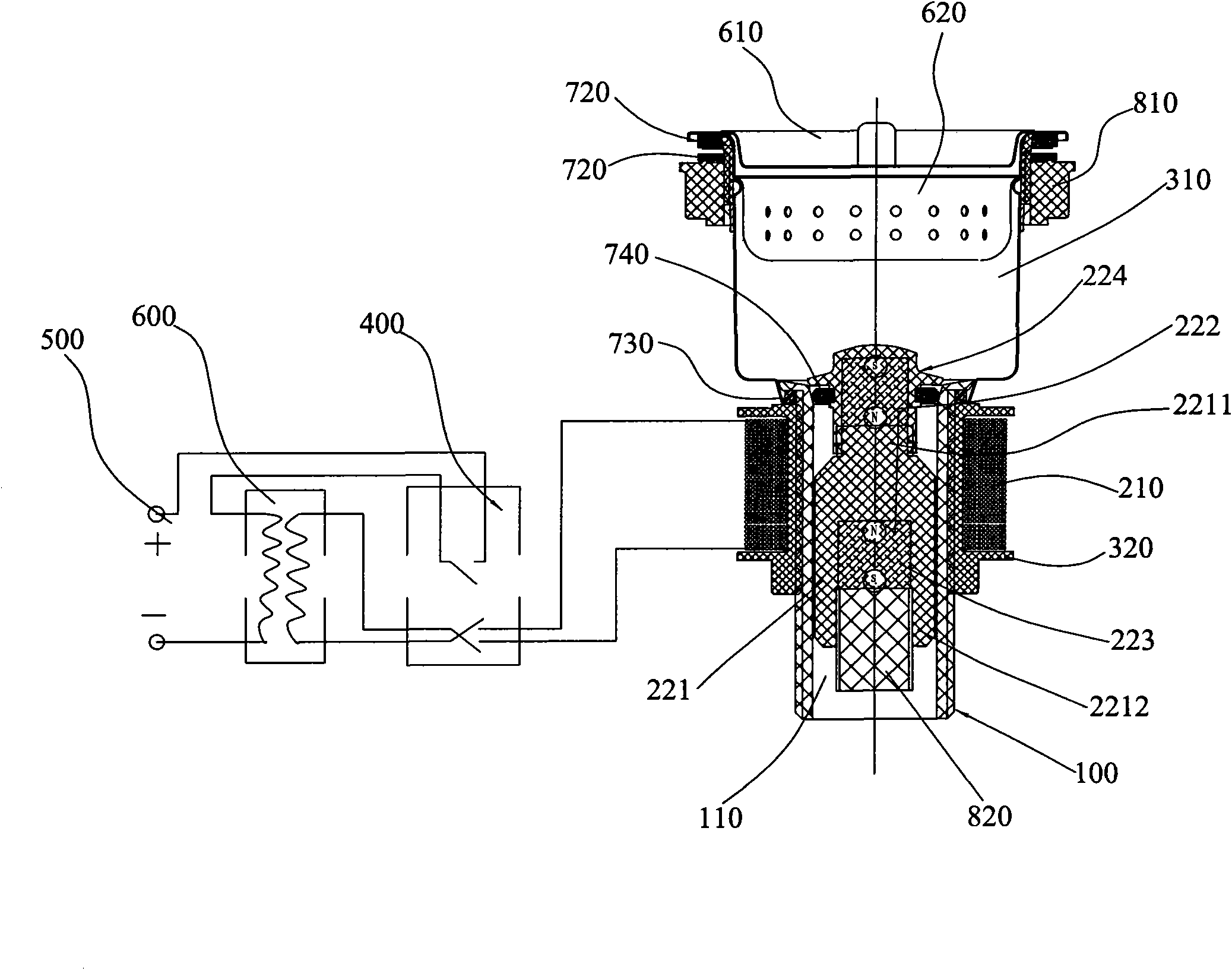
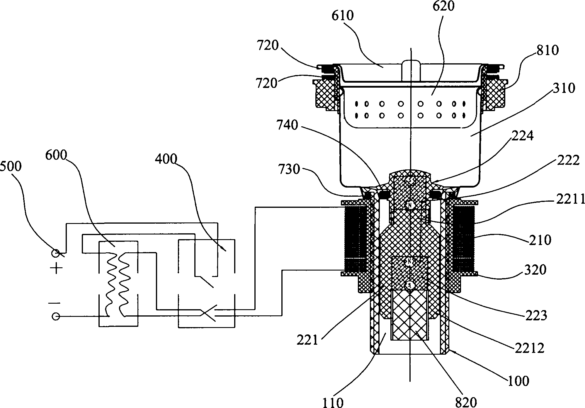
[0034] see Figure 1 to Figure 2 , depicts the electromagnetic drain valve provided by the preferred embodiment of the present invention.

[0035] The electromagnetic drain valve includes a drain pipe 100, a control unit, a body unit, and a water filter unit.

[0036] In the drain pipe 100, a water flow channel 110 connected to a water source is provided;

[0037] The control unit includes a magnetic field generating device 210 and a sliding unit. In this embodiment, the magnetic field generating device 210 includes a switch panel 400, a power supply 500 connected to the switch panel, a voltage stabilizer 600 connected to the power supply 500, and an electromagnetic coil, the electromagnetic coil is sleeved outside the drainpipe 100 And connect with the power supply 500 through the voltage stabilizer 600 and be controlled by it to generate a magnetic field; the sliding unit can slide up and down in the water flow channel 110 of the drain pipe 100, and the sliding unit includ...


PUM


Abstract

The invention discloses an electromagnetic drainer, which comprises a drain pipe and a control unit, wherein the control unit comprises a magnetic field generating device sleeved outside the drain pipe and used for generating a magnetic field, and a sliding unit capable of sliding in the drain pipe vertically; the sliding unit comprises a connecting frame, two magnets arranged on the upper and lower parts of the connecting frame and a sealing unit sleeved with the connecting frame and matching the drain pipe; the magnets corresponds upper and lower ends of the magnetic field generating deviceand the electric field generating device generates magnetic field acting force which applies to the upper and lower magnets in the same direction; and the sealing unit selectively seals or switch on the end port of the drain pipe under the magnetic field acting force along the polarity change of the magnetic field generating device and the two magnets. The drainer is attractive in appearance, compact in structural matching, and more sensitive in work.

Description

technical field [0001] The invention relates to an electromagnetic drainer and a draining method thereof. Background technique [0002] Existing drains currently on the market use the principle of magnetic force, but they seldom use the principle of electromagnetic drive, such as the utility model patent of "Magnetic Automatic Opening and Closing Drain", which uses Two magnets with opposite N poles are used to make the valve seat close the drainage channel. When the weight of the drainage and the weight of the valve seat are greater than the repulsive force, the valve seat opens to drain water. Although it also uses the principle of magnetic force to realize the function of automatic opening and closing of drainage, but in actual use, because the size of the drainage weight cannot be estimated, it will also be difficult to set the magnetic force value that cooperates with it, making the water fall device The opening and closing is not sensitive, which affects the use effect...

Claims


Application Information

Patent Timeline
Patent Type & Authority Applications(China)
IPC IPC(8): E03C1/22E03C1/264
Inventor 林孝山林孝发
Owner JOMOO KITCHEN & BATHROOM
Why Eureka
Try Eureka