Manual slag raking machine

The technology of a slag scraper and a support device is applied in the field of cleaning tools, which can solve problems such as enterprise losses, and achieve the effects of improving the use efficiency, the tool structure is simple, and the economic benefit is improved.

Active Publication Date: 2012-09-26
ANGANG STEEL CO LTD
View PDF0 Cites 0 Cited by
  • Summary
  • Abstract
  • Description
  • Claims
  • Application Information

AI Technical Summary

Problems solved by technology

Stopping the furnace means stopping production, which will cause certain losses to the enterprise

Method used


Image

  • Manual slag raking machine
  • Manual slag raking machine
  • Manual slag raking machine

Examples


Embodiment Construction

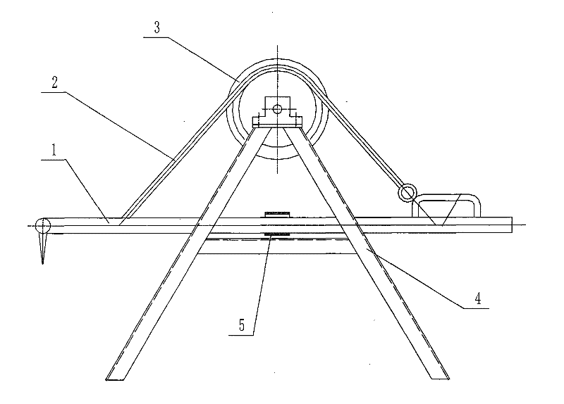
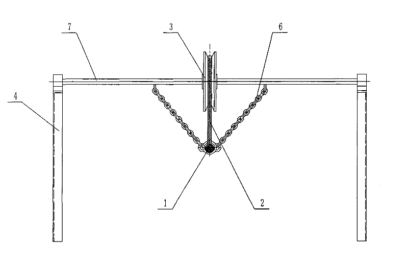
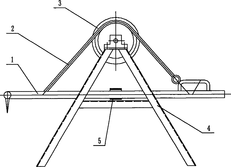
[0011] Manual slag removal machine, such as figure 1 , figure 2 As shown, it includes a supporting device, a positioning device and an iron rake 1, the supporting device includes a pole 7 and a support 4, and the two ends of the pole 7 are vertically fixed with the support 4. The positioning device comprises a pulley 3, a steel rope 2 and a slide chain 6, the pulley 3 is installed in the middle part of the pole 7, the pole 7 on both sides of the pulley 3 is equipped with a slide chain 6, and the bottom ends of the two slide chains 6 are fixed on a sleeve 5, and the sleeve An iron rake 1 is installed in the cylinder 5, and the iron rake 1 on both sides of the sleeve 5 is connected with a steel rope 2, and the iron rake 1 is connected with the pulley 3 through the steel rope 2.

[0012] When removing slag, adjust the steel rope 2 and the zipper 6 so that the iron rake 1 is at the desired height. The operator holds the tail of the iron rake 1 and extends the head of the iron ra...


PUM


Abstract

The invention relates to a manual slag raking machine which comprises a supporting device, a positioning device and an iron rake, wherein the positioning device is mounted on the supporting device; and the iron rake is connected with the supporting device through the positioning device. The manual slag raking machine has reasonable structure design, is convenient to operate, is used for raking slag when a heating furnace is not stopped, and effectively reduces the accumulation of iron sheets, thereby prolonging the cleaning period of the iron sheets and reducing the labor intensity.

Description

technical field [0001] The invention relates to a cleaning tool, in particular to a manual slag removal machine. Background technique [0002] Usually, after the heating furnace heats the steel slab, iron oxide scales are produced, and the iron oxide scales are piled up in a pyramid shape in the heating furnace. To a certain extent, the furnace must be shut down for cleaning. The labor intensity is high, and the cycle is 3-5 months. Shutting down means stopping production, which will cause certain losses to the enterprise. Contents of the invention [0003] The invention overcomes the deficiencies in the prior art and provides a manual slag removal machine with reasonable structural design and convenient use. [0004] In order to solve the above problems, the present invention adopts the following technical solutions: [0005] The manual slag removal machine includes a supporting device, a positioning device and an iron rake, the positioning device is installed on the su...

Claims


Application Information

Patent Timeline
Patent Type & Authority Patents(China)
IPC IPC(8): F27D25/00
Inventor 郭宝安刘金超
Owner ANGANG STEEL CO LTD
Why Eureka
Try Eureka