
High-frequency PWM (pulse width modulation) temperature control device and control method for thermal analyzer

A technology of temperature control device and thermal analyzer, which is applied in the field of thermal analysis, can solve the problems of difficult power control, rough resolution, and high resolution, and achieve the effects of small overshoot, precise temperature control, and high resolution

Inactive Publication Date: 2011-06-29
FUDAN UNIV
View PDF3 Cites 21 Cited by
  • Summary
  • Abstract
  • Description
  • Claims
  • Application Information

AI Technical Summary

Problems solved by technology

However, there is a disadvantage that power control is difficult to achieve higher resolution
If calculated according to my country's 50HZ mains electricity, if the power adjustment period is 10 seconds, the power control resolution can only reach 1 / 600
However, the heating rate of modern thermal analyzers ranges from 0.1 degrees per minute to 100 degrees per minute, and the rough resolution makes it difficult to achieve accurate temperature control.
The SCR conduction angle control method adjusts the power by changing the conduction angle, including trigonometric functions. To achieve linear power adjustment, the calculation of the conduction angle is very large, and the interference caused by the SCR control method is difficult to eliminate
In addition, for the above two temperature control methods, the fluctuation of mains power also has a great influence on the temperature control effect.

Method used


Image

  • High-frequency PWM (pulse width modulation) temperature control device and control method for thermal analyzer
  • High-frequency PWM (pulse width modulation) temperature control device and control method for thermal analyzer
  • High-frequency PWM (pulse width modulation) temperature control device and control method for thermal analyzer

Examples


Embodiment Construction

[0037] The present invention will be further described below in conjunction with accompanying drawing.

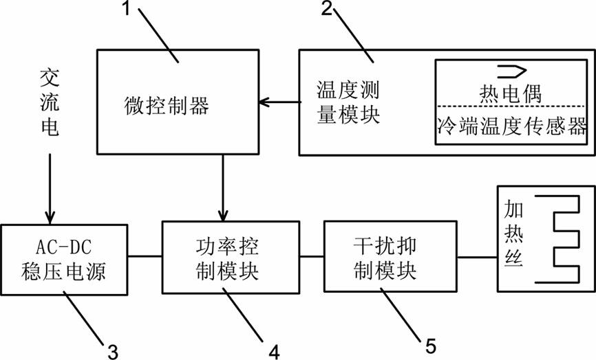
[0038] refer to figure 1 , figure 1 It shows the basic structure of the high-frequency PWM temperature control device of the thermal analyzer, including a microcontroller module 1, a power control module 4 connected to the microcontroller 1, a temperature measurement module 2, and a power control module 4. The connected AC-DC voltage stabilization module 3 and the interference suppression module 5, and the heating wire 6 connected with the interference suppression module 5.

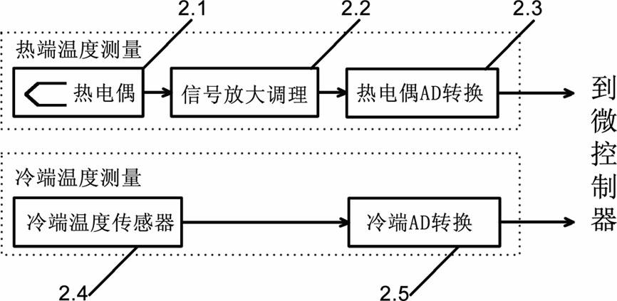
[0039] like figure 2 The thermocouple voltage measurement part in the temperature measurement module 2 includes a thermocouple 2.1, a signal amplification and conditioning unit 2.2 connected to the thermocouple 2.1, and a thermocouple AD conversion unit 2.3 connected to the signal amplification and conditioning unit 2.2. The cold-end temperature measurement part of the temperature measurement modul...


PUM


Abstract

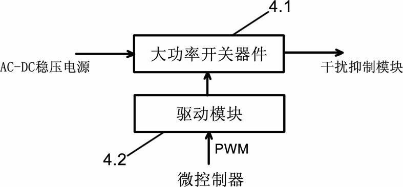
The invention belongs to the technical field of thermoanalysis, in particular to a high-frequency PWM temperature control device and a control method for a thermal analyzer. The temperature control device includes a microcontroller module, a power control module and a temperature measurement module connected with a microcontroller respectively, an AC-DC voltage stabilization module and an interference rejection module connected with the power control module, and a heating wire connected with the interference rejection module; and the temperature measurement module further includes a thermocouple voltage measurement module and a cold junction compensation module. The AC-DC voltage stabilization module is used for converting AC to stable DC, and the power control module is used for receiving high-frequency PWM signals output by the microcontroller; and the microcontroller detects the thermocouple voltage and the cold junction temperature, obtains the actual temperature, and dynamically regulates the duty factor of the PWM signals output by the microcontroller. The invention further provides the control method suitable for the temperature control device, and can realize the high-precision temperature control required by the thermal analyzer.

Description

technical field [0001] The invention belongs to the technical field of thermal analysis, in particular relates to a temperature control device and a control method, in particular to a temperature control device and a control method suitable for a thermal analyzer. Background technique [0002] A thermal analyzer is an instrument that analyzes the relationship between certain physical and chemical changes and temperature rise and fall of a substance during heating or cooling. Commonly used thermal analysis instruments include thermogravimetric analyzer (TGA), differential thermal analyzer (DTA), differential scanning calorimeter (DSC) and thermomechanical analyzer (TMA). The above-mentioned instruments need to adopt the program temperature control method to achieve high-precision temperature control, including constant temperature heating / cooling, constant temperature, and even temperature modulation. The accuracy of temperature control directly affects the analysis results. ...

Claims


Application Information

Patent Timeline
IPC IPC(8): G05D23/22G01N25/00
Inventor 胡运发邹豪杰郭贵兵陈彤兵杨磊
Owner FUDAN UNIV
Learn More