Dual-polarized microstrip antenna

A microstrip antenna, dual-polarization technology, applied in antennas, antenna unit combinations with different polarization directions, antenna arrays, etc., can solve the problems of high cost and difficulty, achieve low cost, improve isolation, and simple implementation Effect

Inactive Publication Date: 2011-06-29
HUAWEI DEVICE CO LTD
View PDF2 Cites 15 Cited by
  • Summary
  • Abstract
  • Description
  • Claims
  • Application Information

AI Technical Summary

Problems solved by technology

[0005] The invention provides a dual-polarized microstrip antenna, which is used to solve the defects of high cost and difficulty in the development and manufacture of high antenna isolation in the prior art. While improving the isolation of the antenna, the cost of development and manufacture is low and easy to implement

Method used


Image

  • Dual-polarized microstrip antenna
  • Dual-polarized microstrip antenna
  • Dual-polarized microstrip antenna

Examples


example 1

[0033] Example 1. The medium of the dual-polarized microstrip antenna is a multilayer dielectric board.

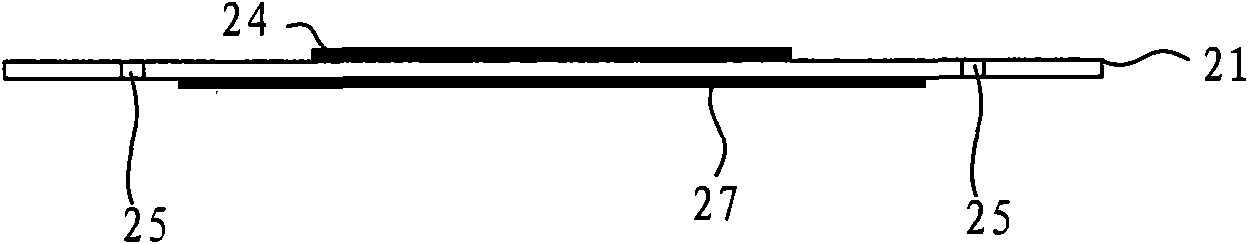
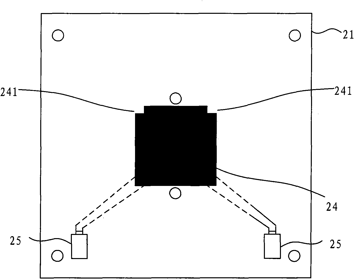
[0034] specifically, Figure 3a It is a schematic diagram of the side view structure of the dielectric plate in the second embodiment of the dual-polarized microstrip antenna of the present invention, Figure 3b It is a schematic diagram of a top view structure of the dielectric plate in the second embodiment of the dual-polarized microstrip antenna of the present invention, Figure 3c It is another top view structural schematic diagram of the dielectric plate in the second embodiment of the dual-polarized microstrip antenna of the present invention, as Figure 3a with Figure 3b As shown, a second dielectric plate 22 is arranged above the first dielectric plate 21; a layer of parasite 23 is arranged on the upper or lower surface of the second dielectric plate 22, as Figure 3c As shown, at least one isolation angle 231 may also be provided on the parasite 23 . Wherein...

example 2

[0035] Example 2. The medium of the dual-polarized microstrip antenna is a multilayer metal plate.

[0036] Specifically, such as Figure 4 As shown, it is a schematic structural diagram of the metal plate in the second embodiment of the dual-polarized microstrip antenna of the present invention, the second metal plate 214 is arranged under the first metal plate 213, and the first metal plate 213 is connected through the feed port to carry out For power feeding, an isolation angle may be set on the first metal plate 213 .

example 3

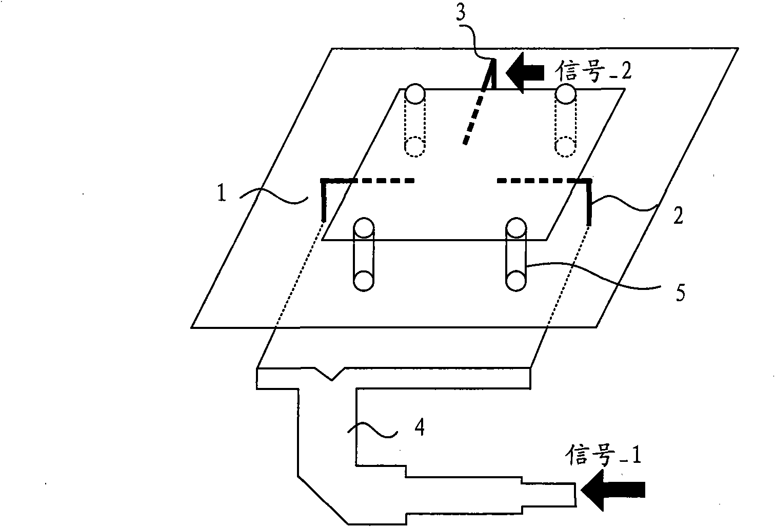
[0037] Example 3. The dual-polarized microstrip antenna is a double-layer or multi-layer structure with coupled feeding.

[0038] Such as Figure 5As shown, it is a structural schematic diagram of the double-layer dual-polarized microstrip antenna for coupling and feeding provided by the second embodiment of the present invention. The upper board 51 includes the radiator 24 of the antenna, which can be a metal plate or a copper-clad dielectric board. The lower board The lower surface of 52 can be a feeder 53 and a feeder port, wherein the upper surface of the lower plate 52 can be a whole piece of metal 54, and suitable slots are slotted on the whole piece of metal 54 on the upper surface of the lower plate 52, which can Double-layer dual-polarized microstrip antennas are used for coupling and feeding. Setting the isolation angle on the radiator 24 can improve the isolation of the dual-polarized antenna. Further, a metal plate or a copper-clad dielectric plate 56 can be adde...


PUM


Abstract

The invention discloses a dual-polarized microstrip antenna which comprises at least one layer of radiating body, wherein the radiating body is connected with two feeding ports; and at least one isolation angle is arranged on the radiating body. In the embodiment of the invention, the isolation angle is arranged on the radiating body of the dual-polarized microstrip antenna, the current distribution of the radiating body can be optimized, and the current which is coupled from one feeding port to the other feeding port is weakened, therefore, the isolation degree between the two feeding ports can be improved, the development and manufacturing costs of the dual-polarized microstrip antenna are low, and the implementation of the dual-polarized microstrip antenna is simple.

Description

technical field [0001] Embodiments of the present invention relate to antenna technology, in particular to a dual-polarized microstrip antenna, which belongs to the technical field of communication. Background technique [0002] Dual-polarized antennas have unique advantages in antenna miniaturization, and are widely used in base station antennas and terminal antennas, especially in multi-antenna systems, such as Multiple-Input Multiple-Output (MIMO) antennas. Generally speaking, dual-polarized antennas require that the two polarized antennas work at the same frequency, and the performance difference should be as small as possible. Therefore, a square radiator with a symmetrical structure is often used. Microstrip antennas are often used to make dual-polarized microstrip antennas because of their low profile, simple processing, good consistency, and easy polarization control. How to improve the isolation between the two polarized antennas is the main problem faced by the du...

Claims


Application Information

Patent Timeline
Patent Type & Authority Applications(China)
IPC IPC(8): H01Q21/24H01Q21/00H01Q9/04H01Q1/38
Inventor 刘兵
Owner HUAWEI DEVICE CO LTD
Why Eureka
Try Eureka