Novel solid insulated switch

A solid insulated switch, a new type of technology, applied in the direction of electric switches, switchgear, switchgear settings, etc., can solve the problems of large size, unfavorable miniaturization and development of electrical equipment, and inability to be interchangeable and universal.

Active Publication Date: 2011-06-29
BEIJING QINGCHANG POWER TECH CO LTD
View PDF7 Cites 17 Cited by
  • Summary
  • Abstract
  • Description
  • Claims
  • Application Information

AI Technical Summary

Problems solved by technology

Among these three wiring schemes, the structures of the solid insulation switches are different and cannot be used interchangeably. The manufacturer needs to set up different molds for the solid insulation switches in different wiring schemes, which increases the production cost.
In the existing three-position solid insulated switch, in order to meet the electrical gap between the isolation terminal and the ground terminal, it is usually necessary to reserve a large space between the isolation terminal and the ground terminal in the solid insulated switch, thus causing the existing The solid insulated switch has a large volume, which is not conducive to the development of miniaturization of electrical equipment

Method used


Image

  • Novel solid insulated switch
  • Novel solid insulated switch

Examples


Embodiment Construction

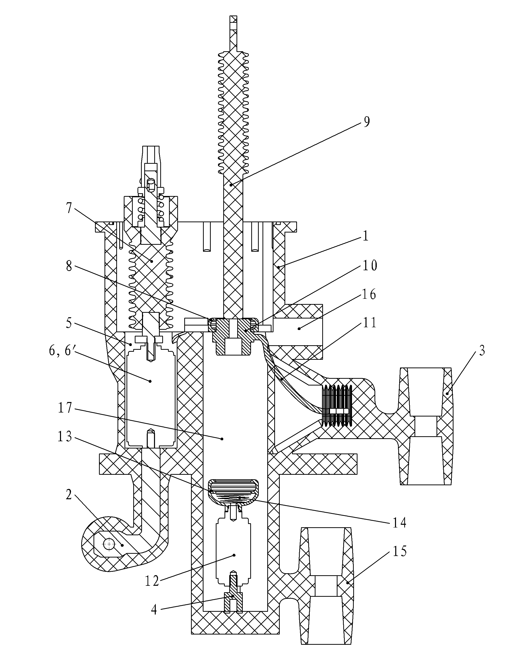
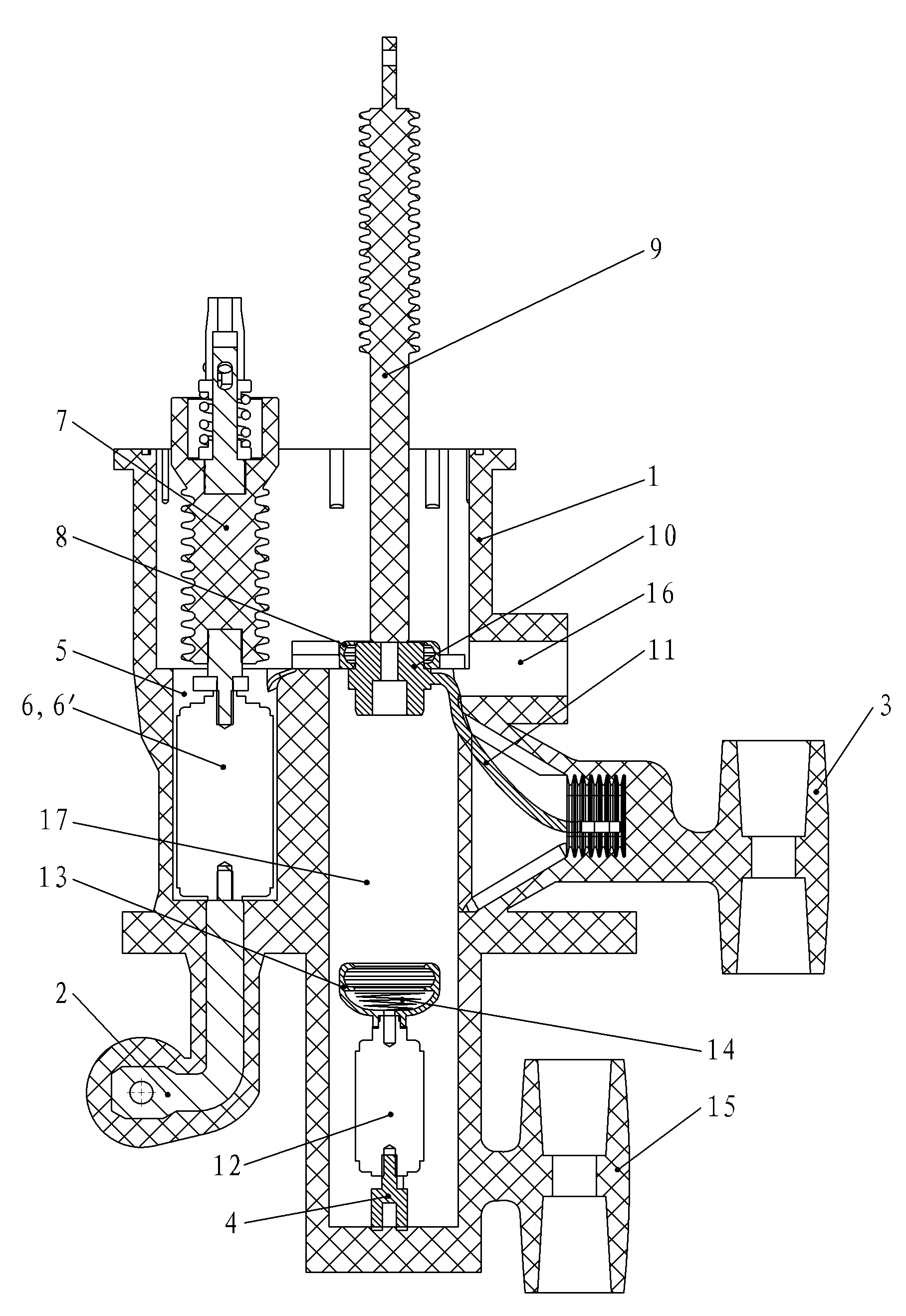
[0011] like figure 1 As shown, the novel solid insulated switch of the present invention includes an insulating shell 1, which is formed integrally with epoxy resin, on which a bus terminal 2, an outlet bushing 3 and a grounding terminal 4 are arranged, and the insulating shell 1 is provided with a first The cavity 5 and the second cavity 17, the first cavity 5 is equipped with a vacuum switch tube 6 for a load switch or a vacuum switch tube 6' for a circuit breaker, the bus terminal 2 and the vacuum switch tube 6 for a load switch or a vacuum switch for a circuit breaker The static contact seat of the switch tube 6' is connected, and a vacuum switch tube control mechanism 7 is arranged above the first cavity 5, and the vacuum switch tube control mechanism 7 is connected to the vacuum switch tube 6 for the load switch or the vacuum switch tube 6' for the circuit breaker. The moving contacts are connected to each other, and are used to control the on-off state of the vacuum swi...


PUM


Abstract

The invention discloses a novel solid insulated switch and relates to an electric switch. The invention aims to provide the solid insulated switch with three working positions, which has a simple structure and high versatility. The novel solid insulated switch comprises an insulating shell, and the insulating shell is provided with a bus wire connecting terminal, a wire outlet bushing, a grounding terminal and a fuse lower interface, wherein a first cavity and a second cavity are formed in the insulating shell; a vacuum switching tube for a load switch or a vacuum switching tube for a breaker is arranged in the first cavity; a vacuum switching tube control mechanism is arranged above the first cavity, and the upper end of the second cavity is provided with an insulating upper end static contact seat; an insulating pull rod is arranged in the second cavity; the inner end of the insulating pull rod is provided with a conductive moving contact; the conductive moving contact is communicated with the wire outlet bushing; the bottom of the second cavity is provided with a vacuum switching tube for grounding; an insulating lower end static contact seat is arranged above the vacuum switching tube for grounding; and the lower part of the insulating lower end static contact seat is provided with a contact spring, and the fuse lower interface is electrically communicated with the insulating lower end static contact seat.

Description

technical field [0001] The invention relates to an electric switch, in particular to a solid insulation switch with good versatility. Background technique [0002] In the existing technology, solid insulated switches are applied to three wiring schemes of 10KV, which are L mode: load switch (load) mode; V mode: circuit breaker mode (vacuum circuit breaker); F mode: load switch + fuse (fuse) mode. Among these three wiring schemes, the solid insulation switches have different structures and cannot be used interchangeably. Manufacturers need to set up different molds for the solid insulation switches in different wiring schemes, which increases the production cost. In the existing three-position solid insulated switch, in order to meet the electrical gap between the isolation terminal and the ground terminal, it is usually necessary to reserve a large space between the isolation terminal and the ground terminal in the solid insulated switch, thus causing the existing The soli...

Claims


Application Information

Patent Timeline
Patent Type & Authority Applications(China)
IPC IPC(8): H02B13/00H02B1/04H02B1/20H02B1/26H01H33/66H01H31/00
Inventor 张焕粉
Owner BEIJING QINGCHANG POWER TECH CO LTD
Why Eureka
Try Eureka