
Process and apparatus for separating solids from gas

A technology of separation and gas outlet, applied in the direction of separation method, dispersed particle separation, chemical instrument and method, etc., can solve the problems of internal corrosion of metal cyclone, damage to cyclone, etc.

Inactive Publication Date: 2011-06-29
UOP LLC
View PDF5 Cites 6 Cited by
  • Summary
  • Abstract
  • Description
  • Claims
  • Application Information

AI Technical Summary

Problems solved by technology

[0007] Because the cyclone handles a large mixture of small solids and gas, the interior of the metal cyclone will be corroded, which can damage the cyclone

Method used


Image

  • Process and apparatus for separating solids from gas
  • Process and apparatus for separating solids from gas
  • Process and apparatus for separating solids from gas

Examples


Embodiment Construction

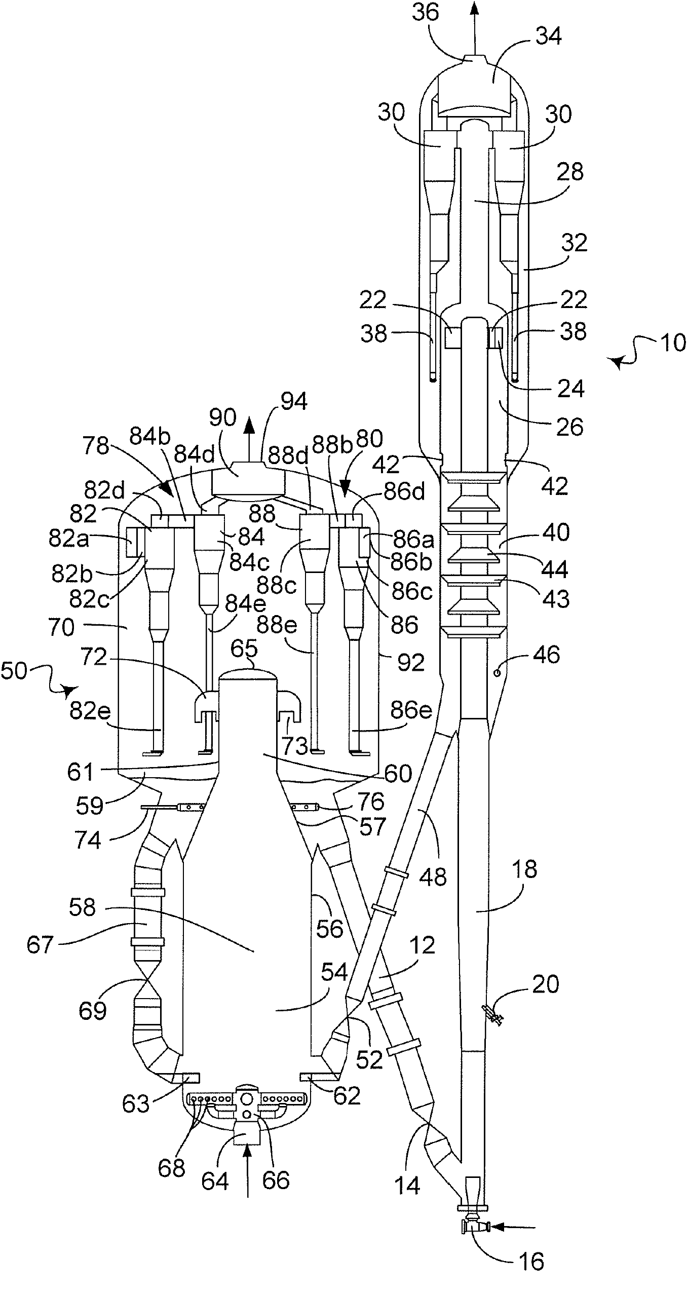
[0012] Although the apparatus and method of the present invention can be used in any solid-gas separation plant, it is immediately applicable in an FCC unit. figure 1 An FCC unit comprising a reactor vessel 10 and a regenerator vessel 50 is shown. Regenerator standpipe 12 conveys catalyst from regenerator vessel 50 to reactor riser 18 at a rate regulated by slide valve 14 . A fluidizing medium—such as steam from nozzle 16—conveys the catalyst at a higher density upward through riser 18 until a plurality of feed injection nozzles 20 (only one shown) are injected transversely to the flow stream of catalyst particles. material.

[0013] Suitable feeds are conventional FCC feeds or higher boiling hydrocarbon feeds. One of the most common of such conventional feedstocks is "vacuum gas oil" (VGO), which is vacuum fractionated atmospheric slag typically boiling between 343 and 552°C (650 and 1025°F). Hydrocarbon materials for the preparation of oil. In this fraction, there are ge...


PUM

PropertyMeasurementUnit
boiling pointaaaaaaaaaa
densityaaaaaaaaaa

Abstract

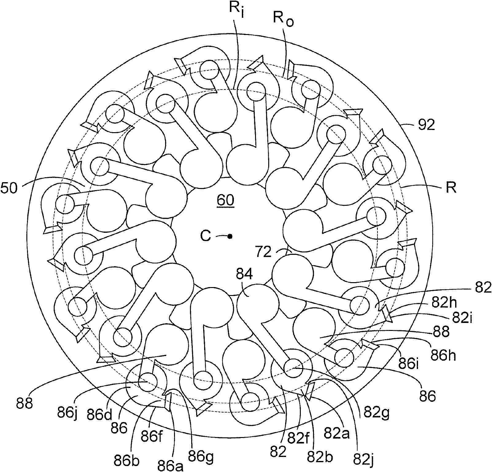
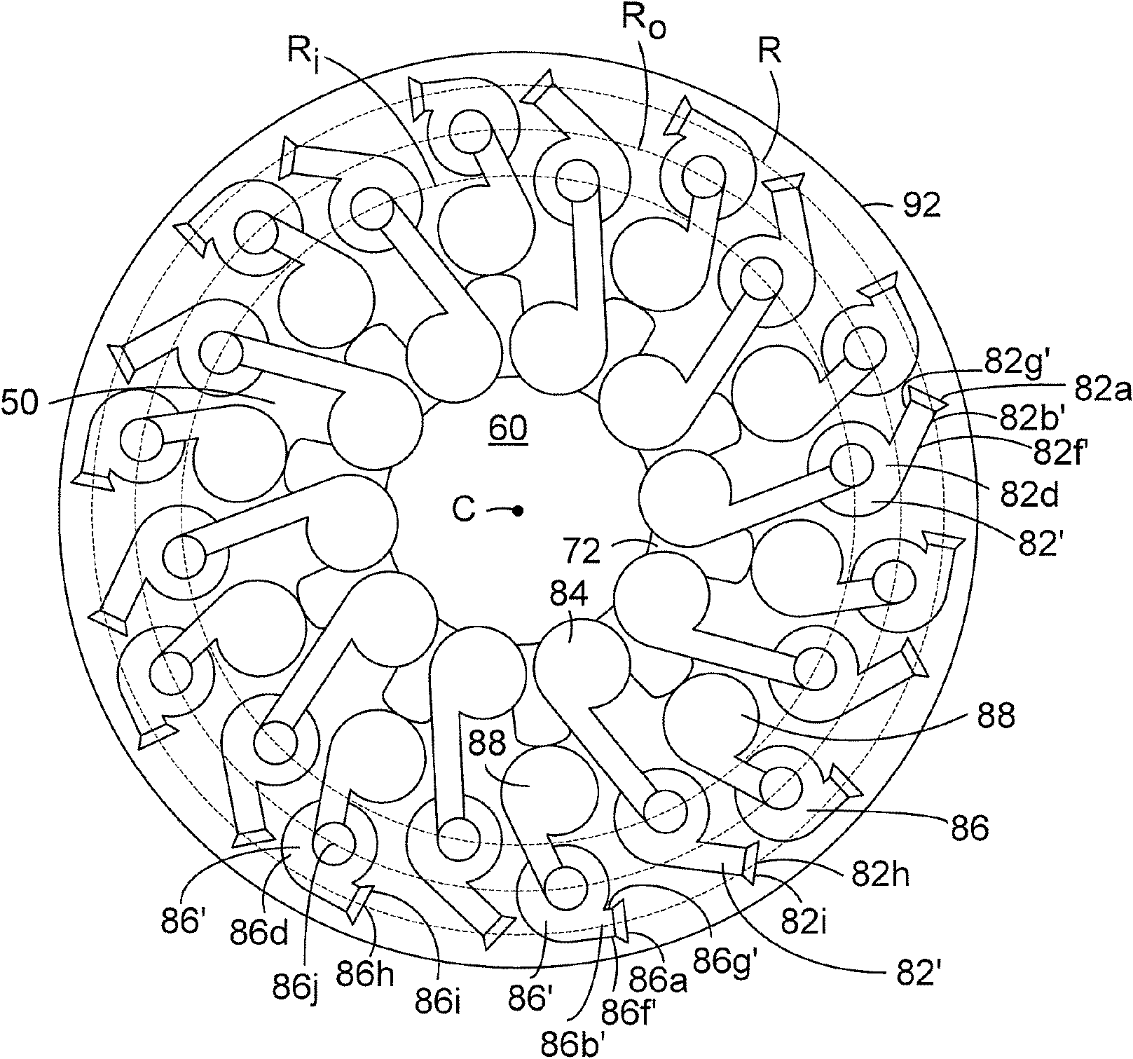
The invention discloses a process and an apparatus that separate solids from gas in a vessel using cyclones. The cyclones have centers located at different distances from a center of the vessel, but the inlets to the cyclones are located at the same distance from the center to balance the proportions of catalyst fines entering each cyclone.

Description

technical field [0001] The present invention relates to an apparatus and method for separating solid particles from gases. The invention relates in particular to the separation of catalyst particles from product or combustion gases in the field of fluid catalytic cracking (FCC). Background technique [0002] FCC is a hydrocarbon conversion process which is achieved by contacting hydrocarbons in a fluidized reaction zone with a catalyst consisting of finely divided particulate material. In contrast to hydrocracking, catalytic cracking reactions are carried out without significant addition or consumption of hydrogen. As the cracking reaction proceeds, large amounts of high-carbon material known as coke are deposited on the catalyst. In the reactor vessel, vaporous products are separated from the spent catalyst. The spent catalyst is stripped with an inert gas, such as steam, to strip entrained hydrocarbon-containing gases from the spent catalyst. A high temperature regener...

Claims


Application Information

Patent Timeline
Patent Type & Authority Applications(China)
IPC IPC(8): B01D45/12B04C9/00
CPCC10G11/18B04C5/26B01D45/12B04C5/28
Inventor R·L·梅尔柏格
Owner UOP LLC
Learn More