Suction cooling device for production of polyester and nylon composite filaments

A technology of polyester-nylon composite yarn and cooling device, which is applied to household refrigeration devices, cooling fluid circulation devices, coolers, etc., can solve the problems of inability to vacuum the composite yarn, environmental protection, poor cooling effect, etc., so as to improve the cooling effect. , The effect of uniform cooling and avoiding environmental pollution

Active Publication Date: 2021-11-19
苏州申久高新纤维有限公司
View PDF6 Cites 2 Cited by
  • Summary
  • Abstract
  • Description
  • Claims
  • Application Information

AI Technical Summary

Problems solved by technology

[0004] The purpose of the present invention is to solve the shortcomings of the existing suction cooling device, which has poor refrigeration effect and cannot perform dust collection and environmental protection on the composite yarn, and proposes a suction cooling device for the production of polyester nylon composite yarn

Method used


Image

  • Suction cooling device for production of polyester and nylon composite filaments
  • Suction cooling device for production of polyester and nylon composite filaments
  • Suction cooling device for production of polyester and nylon composite filaments

Examples


Embodiment 1

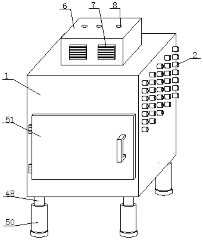
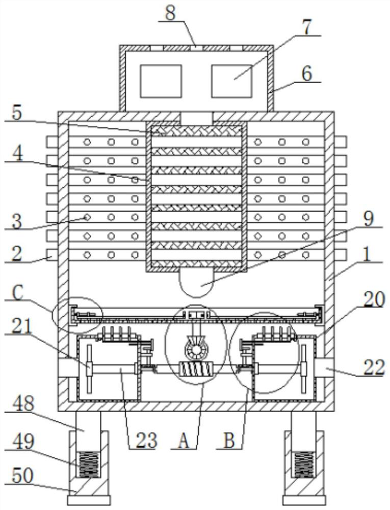
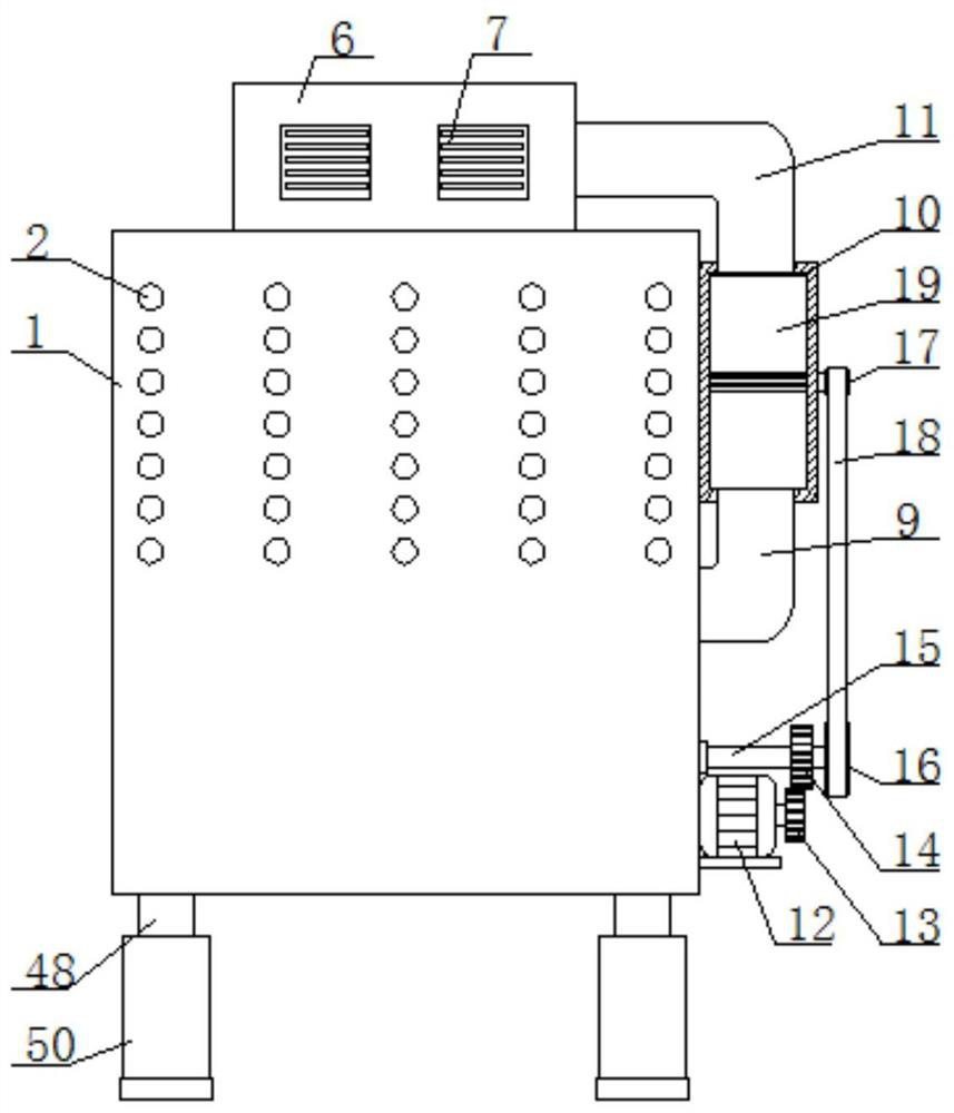
[0031] refer to Figure 1-7, a suction cooling device for the production of polyester-nylon composite yarn, comprising a refrigeration cabinet 1, a case cover 51 is installed on the front of the refrigeration cabinet 1, a plurality of guide wire pipes 2 are arranged in the refrigeration cabinet 1, and a Cooling box 4, a plurality of wire guide tubes 2 are located in the cooling box 4, the cooling box 4 is filled with insulation cotton 5, the insulation cotton 5 is wrapped on the outside of the wire guide tube 2, and the outside of the wire guide tube 2 is provided with a plurality of air holes 3. A plurality of air holes 3 are located on the outside of the cooling box 4. The top of the cooling box 4 is connected to a refrigeration mechanism. The outside of the refrigeration cabinet 1 is connected to a suction cylinder 10. A propeller 19 is installed in the suction cylinder 10, and the suction cylinder The bottom of 10 communicates with the bottom of the cooling box 4 with a su...

Embodiment 2

[0047] refer to Figure 1-7 , a suction cooling device for the production of polyester-nylon composite yarn, comprising a refrigeration cabinet 1, a case cover 51 is installed on the front of the refrigeration cabinet 1, a plurality of guide wire pipes 2 are arranged in the refrigeration cabinet 1, and a Cooling box 4, a plurality of wire guide tubes 2 are located in the cooling box 4, the cooling box 4 is filled with insulation cotton 5, the insulation cotton 5 is wrapped on the outside of the wire guide tube 2, and the outside of the wire guide tube 2 is provided with a plurality of air holes 3. A plurality of air holes 3 are located on the outside of the cooling box 4. The top of the cooling box 4 is connected to a refrigeration mechanism. The outside of the refrigeration cabinet 1 is connected to a suction cylinder 10. A propeller 19 is installed in the suction cylinder 10, and the suction cylinder The bottom of 10 communicates with the bottom of the cooling box 4 with a s...


PUM


Abstract

The invention belongs to the technical field of cooling of polyester and nylon composite filaments, particularly relates to a suction cooling device for production of polyester and nylon composite filaments. The problems that an existing suction cooling device is poor in refrigeration effect and cannot perform dust collection and environmental protection on the composite filaments are solved. According to the following scheme, the suction cooling device comprises a refrigeration cabinet, and a box cover is rotationally mounted on the front surface of the refrigeration cabinet; a plurality of wire guide pipes are arranged in the refrigeration cabinet, a cooling box is arranged in the refrigeration cabinet, the wire guide pipes are all located in the cooling box, the cooling box is filled with heat preservation cotton, and the outer sides of the wire guide pipes are wrapped with the heat preservation cotton; and a plurality of air holes are formed in the outer sides of the wire guide pipes, the air holes are all located in the outer side of the cooling box, the top of the cooling box communicates with a refrigeration mechanism, the outer side of the refrigeration cabinet communicates with an air suction cylinder, and a propeller is rotationally installed in the air suction cylinder. The suction cooling device is convenient to operate, the refrigeration effect is improved, cooling is uniform, dust collection can be carried out on the composite filaments, and dust collection and environmental protection are carried out.

Description

technical field [0001] The invention relates to the technical field of cooling polyester and nylon composite yarns, in particular to a suction cooling device for producing polyester and nylon composite yarns. Background technique [0002] The production of polyester / nylon composite yarn needs to be heated during production. After heating, the polyester / nylon composite yarn enters the cooling device for cooling. The filament cooling system often used in chemical fiber factories is mainly composed of three parts, namely the exhaust cooling device, the cooling plate, and the exhaust. The smoke main pipe, the silk strips come out of the first heat box and are close to the surface of the draft cooling device, and then to the cooling plate. The surface of the thread path of the draft cooling device is provided with more air extraction pores, and the lower end is provided with an air extraction port, for example, The publication (announcement) number: CN206692786U's patent document...

Claims


Application Information

Patent Timeline
Patent Type & Authority Applications(China)
IPC IPC(8): F25D15/00F25D17/08F25D23/00F25B21/02
CPCF25D15/00F25D17/08F25D23/00F25B21/02Y02P70/62
Inventor 孔刚
Owner 苏州申久高新纤维有限公司
Why Eureka
Try Eureka