
Method for modeling control circuit for processing machine

A technology for regulating loops and processors, applied to printing machines, general parts of printing machinery, printing, etc., can solve problems such as insufficient to achieve optimal results, interference characteristics, and no adjustments, so as to save manual input and avoid The effect of important error sources

Inactive Publication Date: 2011-06-29
ROBERT BOSCH GMBH
View PDF2 Cites 0 Cited by
  • Summary
  • Abstract
  • Description
  • Claims
  • Application Information

AI Technical Summary

Problems solved by technology

[0008] In time-continuous regulation, the problem is that the time constant is inversely proportional to the speed
[0009] The known methods have the disadvantage that on the one hand adjustment parameters have to be entered manually, which usually does not lead to optimal adjustment, and on the other hand the methods for automatic adaptation are not yet sufficient to achieve optimal results, especially Optimal Results on Disturbance Properties

Method used

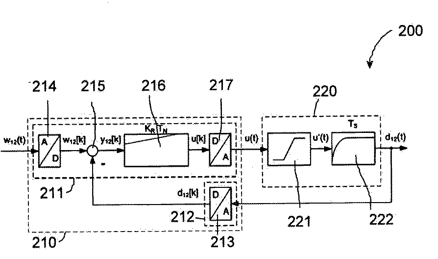
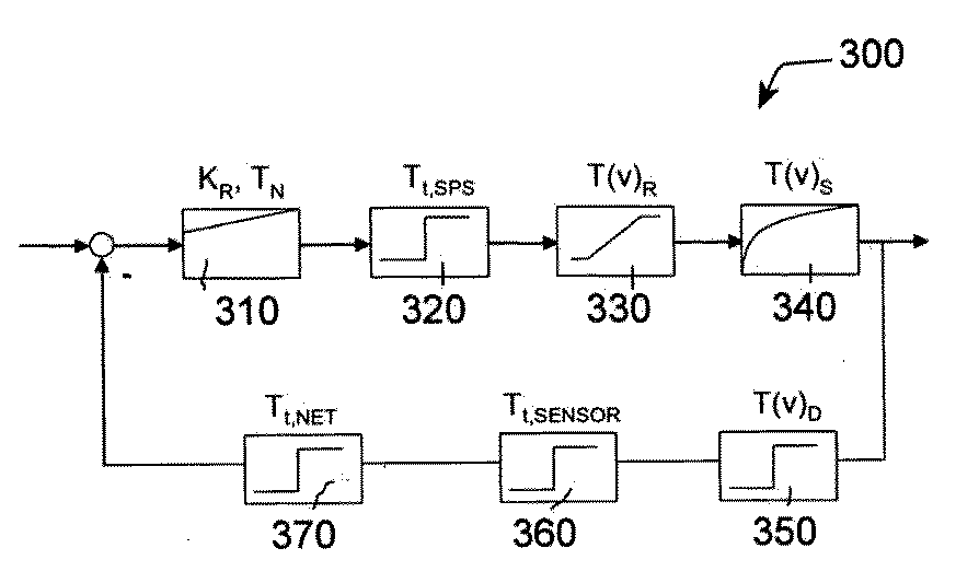

Image

  • Method for modeling control circuit for processing machine
  • Method for modeling control circuit for processing machine
  • Method for modeling control circuit for processing machine

Examples


Embodiment Construction

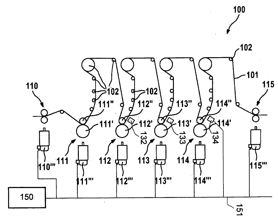
[0031] exist figure 1 A processing machine configured as a printing press is generally indicated with 100 . Printed material, such as paper 101 , is fed to the machine by an infeed 110 . The paper 101 is guided and printed by processing devices designed as printing units 111 , 112 , 113 , 114 and is output again by an outfeed 115 . The in-feed, out-feed and printing means are arranged positionally, in particular cylindrically or angularly. The printing units 111 to 114 are located in the region of the rail voltage regulation between the inlet unit 110 and the outlet unit 115 .

[0032] The printing units 111 to 114 each have impression cylinders 111' to 114', which bear against the respective top rollers 111'' to 114'' with great pressure. The impression cylinders can be driven individually and independently. The associated drives 111''' to 114''' are shown schematically. The pressure roller is designed to be freely rotatable. The printing units 111 to 114 each form a fr...


PUM


Abstract

The invention relates to modeling a control circuit (300) for a processing machine for processing a material web, particularly shaft-less printing machine, wherein at least one dead time (Tt,SENSOR, Tt,NET, Tt,SPS, T(v)R, T(v)D) is taken into consideration during modeling.

Description

technical field [0001] The invention relates to a method for modeling a control loop of a processor, a correspondingly designed computing unit, a corresponding computer program and a corresponding computer program product. [0002] Although the following mainly refers to printing machines, the invention is not restricted thereto, but can be directed to all types of handling machines in which goods rails or material rails are processed. However, the invention can be used in particular in printing presses such as newspaper printing presses, odd-print printing presses, gravure printing presses, packaging printing presses or securities printing presses, as well as in processing machines such as bag making machines, envelope machines or in the packaging machine. Cargo rails may be constructed from paper, stock, cardboard, plastic, metal, rubber in film form, and the like. Background technique [0003] In the processing machines involved, in particular printing presses, the good...

Claims


Application Information

Patent Timeline
Patent Type & Authority Applications(China)
IPC IPC(8): B41F33/00
CPCB41F33/0036B41F33/0081
Inventor S·舒尔茨H·施纳贝
Owner ROBERT BOSCH GMBH
Learn More