
Electrical circuit arrangement

A circuit arrangement and printed circuit board technology, applied in the field of light-emitting devices, can solve problems such as the inability to achieve a cylindrical shape or a high protrusion, and the limitation of the implementation of signal lights.

Inactive Publication Date: 2011-06-29
FHF FUNKE HUSTER FERNSIG
View PDF1 Cites 0 Cited by
  • Summary
  • Abstract
  • Description
  • Claims
  • Application Information

AI Technical Summary

Problems solved by technology

[0007] In the prior art, the printed circuit board with the LEDs on it can or must be arranged directly on the cooling block, whereby the possible embodiments of the signal lamp are limited
In particular, cylindrical or highly protruding signal lamps with elongated housings are therefore hardly realizable

Method used


Image

  • Electrical circuit arrangement
  • Electrical circuit arrangement
  • Electrical circuit arrangement

Examples


Embodiment Construction

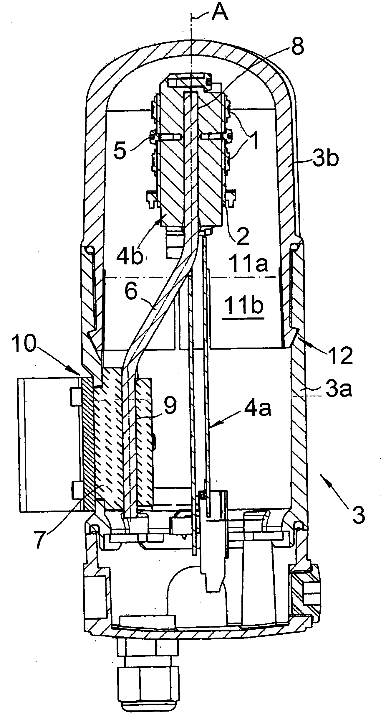
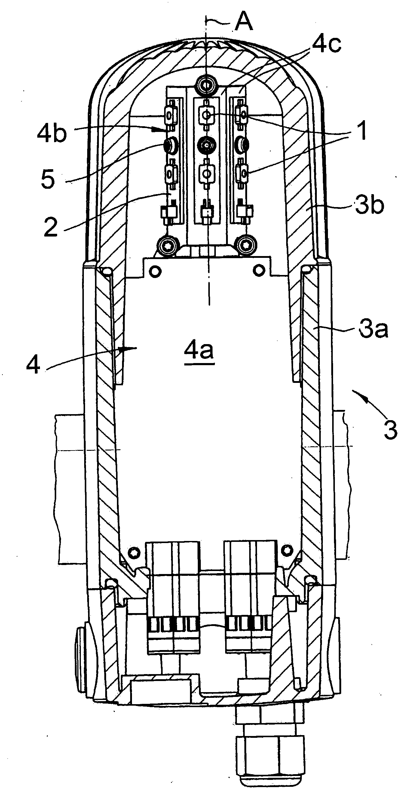
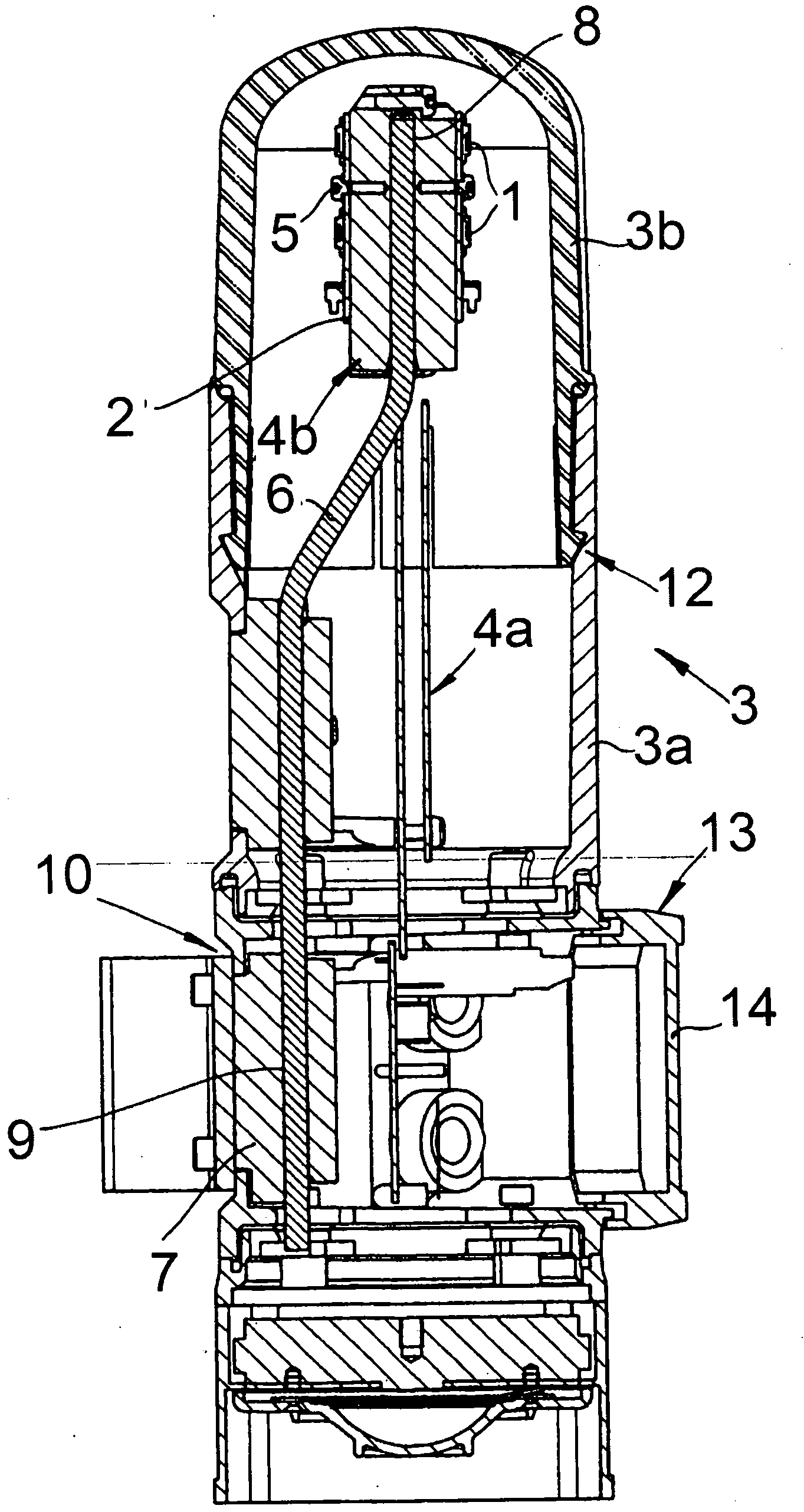
[0026]The drawing shows an electrical circuit arrangement which is used in potentially explosive atmospheres. This circuit arrangement is a signal circuit arrangement, in the above case a signal lamp. The circuit arrangement or the basic structure of the signal lamp comprises one or more electrical components 1 , which in each case are LEDs. The component 1 or LED 1 is accommodated on a printed circuit board 2 made of thermally conductive material. In an embodiment, the printed circuit board 2 is made of metal, especially aluminium. LED 1 refers to SMD-LED 1 .

[0027] Will figure 1 and 2 A comparison reveals that the arrangement of the LDE or light emitting device 1 is annular compared to the central axis A of the housing 3 . The housing 3 is arranged rotationally symmetrically with respect to this axis A. As shown in FIG. In this way, the light radiated from the LED or lighting device 1 is emitted in the entire spatial direction, so that an all-round light emission is ...


PUM


Abstract

The present invention relates to an electrical circuit arrangement, in particular an electrical signal circuit arrangement and preferably a signal lamp which is used in hazardous areas. The circuit arrangement is equipped with at least one electrical component (1) which is arranged on a printed circuit board (2) produced from a heat-conducting material. The electrical component (1) is, in particular, a luminous means (1). A cooling device (6, 7) which is in thermal contact with the printed circuit board (2) is also realized. According to the invention, the cooling device (6, 7) is in at least two parts, with a heat sink (7) and at least one heat pipe (6). In this case, the heat pipe (6) thermally connects the printed circuit board (2) to the heat sink (7).

Description

technical field [0001] The invention relates to a circuit arrangement, in particular an electrical signal circuit arrangement, preferably a signal lamp for use in areas at risk of explosion, which circuit arrangement has at least one printed circuit board arranged on a heat-conducting material The electrical components on the circuit board, especially the lighting device, and have a cooling device that maintains a thermal connection with the printed circuit board. The light emitting device arranged on the printed circuit board usually involves one or more LEDs. Background technique [0002] Signal lights are commonly used to generate one or more visual signals, which are used to indicate possible dangers, abnormal conditions, etc. Therefore, signal lights are used, for example, to report and warn of machine malfunctions. Likewise, signal lights can also indicate evacuation routes or, in some cases, billboards. The same applies to acoustic signaling devices, which, as desc...

Claims


Application Information

Patent Timeline
Patent Type & Authority Applications(China)
IPC IPC(8): F21V25/12F21V29/00F21S8/00F21W131/403
CPCF21V29/2206F21V23/06F21V29/004F21W2111/00F21Y2111/005F21Y2101/02F21V29/006F21V25/12F21V29/74F21Y2115/10F21Y2107/30F21V29/51
Inventor 杰克·布龙诺维茨贝恩哈德·罗默
Owner FHF FUNKE HUSTER FERNSIG
Learn More