Air conditioner

A technology of air-conditioning device and flow control device, which is applied in the direction of air-conditioning system, high-efficiency regulation technology, space heating and ventilation, etc. It can solve the problem of large transmission power and achieve the effect of reducing transmission power

Active Publication Date: 2011-06-29
MITSUBISHI ELECTRIC CORP
View PDF6 Cites 1 Cited by
  • Summary
  • Abstract
  • Description
  • Claims
  • Application Information

AI Technical Summary

Problems solved by technology

Therefore, if the circulation path becomes longer, the delivery power becomes very large

Method used


Image

  • Air conditioner
  • Air conditioner
  • Air conditioner

Examples


Embodiment approach 1

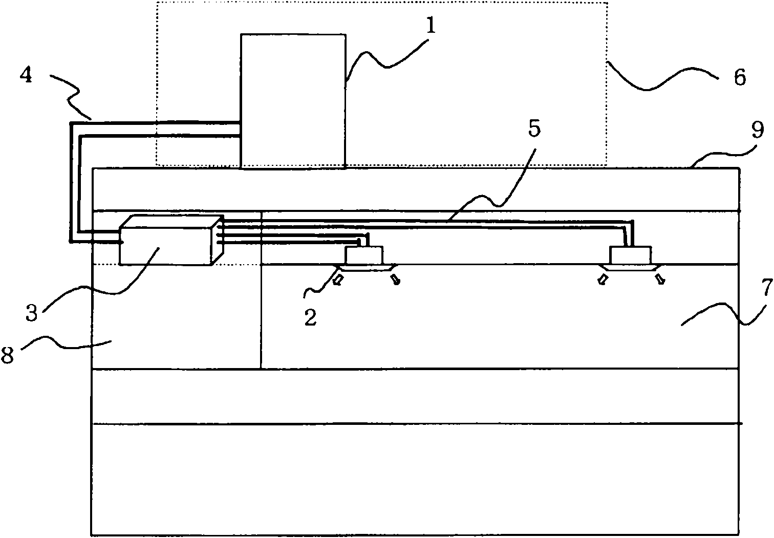
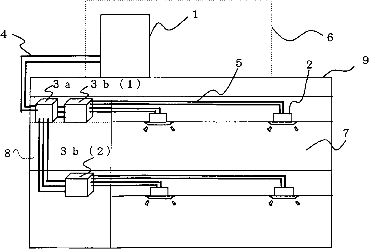
[0025] figure 1 It is a figure which shows the installation example of the air conditioner which concerns on embodiment of this invention. figure 1 The air conditioner has an outdoor unit 1 as a separate unit, one or more indoor units 2, and a relay unit 3, the outdoor unit 1 is used as a heat source device, and the indoor unit 2 performs air conditioning in the air-conditioning target space, The relay unit 3 performs heat exchange between the refrigerant and a heat-transporting medium (hereinafter referred to as heat medium) different from the refrigerant, and relays heat transfer. The outdoor unit 1 and the relay unit 3 are connected by a refrigerant pipe 4 for circulating a refrigerant such as a quasi-azeotropic refrigerant such as R-410A or R-404A to transfer heat. In addition, between the relay unit 3 and the indoor unit 2, in order to circulate heat mediums such as water, water added with non-volatile or low-volatile preservatives within the air-conditioning temperature...

Embodiment approach 2

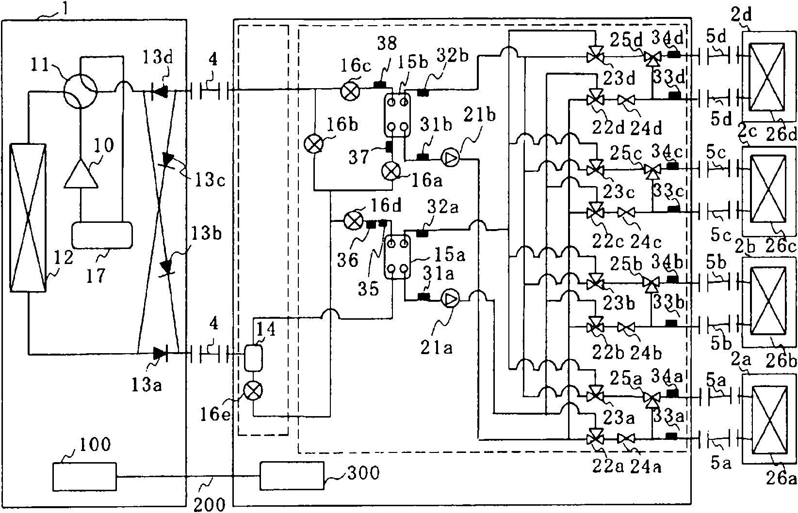
[0121] Figure 10 It is a figure which shows the structure of the air-conditioning apparatus of Embodiment 2. exist Figure 10 Among them, the flow meters 41 a , 41 b , 41 c , and 41 d detect the flow rates of heat medium flowing into the use-side heat exchangers 26 a to 26 d , respectively, and transmit the signals of the flow values ​​to the relay unit side control device 300 . In this embodiment, for example, by providing the flow meters 41a to 41d, the relay unit side control device 300 can obtain the flow rate value of the heat medium flowing through the use side heat exchangers 26a to 26d. Furthermore, based on the flow rate of the heat medium flowing through the use-side heat exchangers 26a-26d, the detection temperatures of the third temperature sensors 33a-33d, and the detection temperatures of the fourth temperature sensors 34a-34d, the relay unit side control device 300 can The aforementioned (1) formula calculates the heat load of the use side heat exchangers 26a...

Embodiment approach 3

[0130] In the above-mentioned first embodiment, the refrigerant of the quasi-azeotropic mixture refrigerant has been described as the refrigerant circulating in the refrigeration cycle, but the present invention is not limited thereto. Single refrigerants such as R-22 or R-134a, non-azeotropic mixed refrigerants such as R-407C, and CF containing double bonds in the chemical formula can also be used. 3 CF=CH 2 A refrigerant having a relatively small value of the global warming coefficient and a mixed refrigerant containing the refrigerant, CO 2 or natural refrigerants such as propane, etc.

[0131] Furthermore, in the air-conditioning apparatus of the above-mentioned embodiment, the storage unit 17 is provided in the refrigeration cycle, but the storage unit 17 may not be provided, for example. The check valves 13a to 13d are also not an essential mechanism, so even if the refrigeration cycle is configured without using the check valves 13a to 13d, the same operation can be p...


PUM


Abstract

The present invention provides an air conditioner in which the refrigerant is adapted not to flow up to an indoor unit to further save energy. The air conditioner has a refrigeration cycle circuit formed by interconnecting by piping a compressor (10) for pressuring the refrigerant, a four-way valve (11) for switching a refrigerant circulation path, a heat source-side heat exchanger (12), an expansion valve (16a-16e) for regulating the pressure of the refrigerant, and intermediate heat exchangers (15a, 15b) for heating and cooling a heat medium by exchanging heat between the heat medium and the refrigerant. A heat medium circuit is formed by interconnecting by piping the intermediate heat exchangers (15a, 15b), a pump (21a, 21b) for pressurizing the heat medium, utilization-side heat exchangers (26a-26d) for exchanging heat between the heat medium and air in an indoor space (7), and a flow path switching valve (22a-22d, 23a-23d) for allowing the passage of heated heat medium to each utilization-side heat exchanger (26a-26d) or the passage of cooled heat medium to each utilization-side heat exchanger (26a-26d).

Description

technical field [0001] The present invention relates to an air conditioner used for, for example, a complex air conditioner for a building or the like. Background technique [0002] In an air-conditioning apparatus such as a multi-type air conditioner for a building, for example, a refrigerant is circulated between an outdoor unit that is a heat source unit disposed outside a building and an indoor unit disposed indoors of the building. Then, the refrigerant radiates and absorbs heat, and cools or heats the air-conditioning target space through the heated and cooled air. As the refrigerant, for example, HFC (hydrofluorocarbon) refrigerants are often used. In addition, carbon dioxide (CO 2 ) and other natural refrigerant proposals. [0003] Furthermore, in an air conditioner called a chiller, cold or warm heat is generated by a heat source unit arranged outside a building. Then, the heat exchanger installed in the outdoor unit heats and cools water, antifreeze, etc., and ...

Claims


Application Information

Patent Timeline
Patent Type & Authority Applications(China)
IPC IPC(8): F24F11/02
CPCF25B2313/0231F25B13/00Y02B30/745F24F3/06F25B2313/0272F25B2700/13F24F2011/0043F25B2600/13F24F2011/0045F25B25/005F25B2313/02741F24F2140/12F24F2140/20Y02B30/70
Inventor 山下浩司森本裕之本村祐治鸠村杰田中直树若本慎一冈崎多佳志岛津裕辅
Owner MITSUBISHI ELECTRIC CORP
Why Eureka
Try Eureka