
Embedded fixed type lifting handle structure of pot

A fixed handle seat technology, applied in the field of embedded fixed pot handle structure, can solve the problems of screw looseness, loss of view, falling off, etc., to achieve the effect of avoiding loosening, improving viewability and ensuring safety

Active Publication Date: 2012-09-05
CHANGSHU KASMAIN
View PDF0 Cites 2 Cited by
  • Summary
  • Abstract
  • Description
  • Claims
  • Application Information

AI Technical Summary

Problems solved by technology

Fixing the pot handle and the handle seat is prone to the following disadvantages: first, the installation efficiency is low, and the labor intensity of the assembly workers is high; There is looseness or even falling off, so that the handle appears to swim and sway relative to the handle seat; the third is a potential safety hazard, because once the screw is suddenly loosened, the pot body and the handle are separated, and the hot food in the pot body is overturned and scalded. and the cook; the fourth is that the screws are exposed and detrimental to the view
[0003] The applicant has searched the patent documents, but there is no technical revelation that can fully remedy the above-mentioned shortcomings in the published Chinese patent documents. For this reason, the applicant has carried out active and beneficial explorations. The technology to be introduced below It is in this situation that the program emerges

Method used


Image

  • Embedded fixed type lifting handle structure of pot
  • Embedded fixed type lifting handle structure of pot
  • Embedded fixed type lifting handle structure of pot

Examples


Embodiment Construction

[0014] In order to enable the examiners of the patent office, especially the public, to understand the technical essence and beneficial effects of the present invention more clearly, the applicant will describe in detail the following in the form of examples, but none of the descriptions to the examples is an explanation of the solutions of the present invention. Any equivalent transformation made according to the concept of the present invention which is merely formal but not substantive shall be regarded as the scope of the technical solution of the present invention.

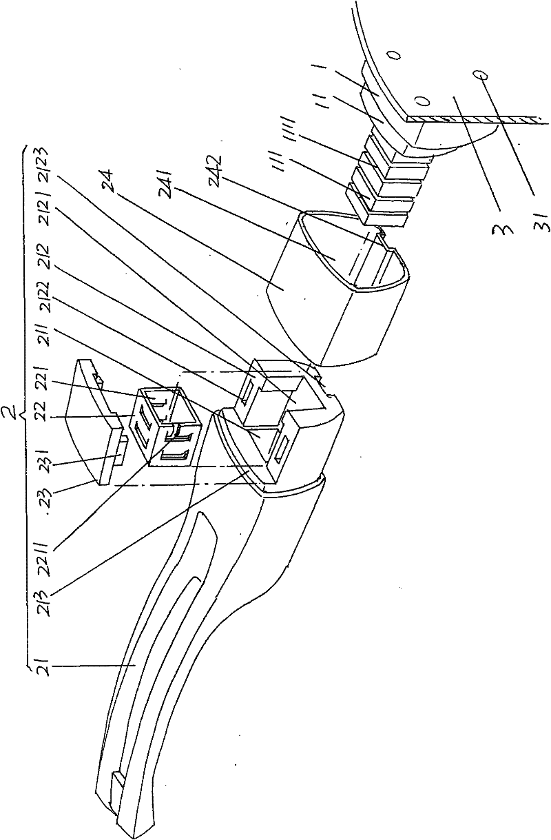
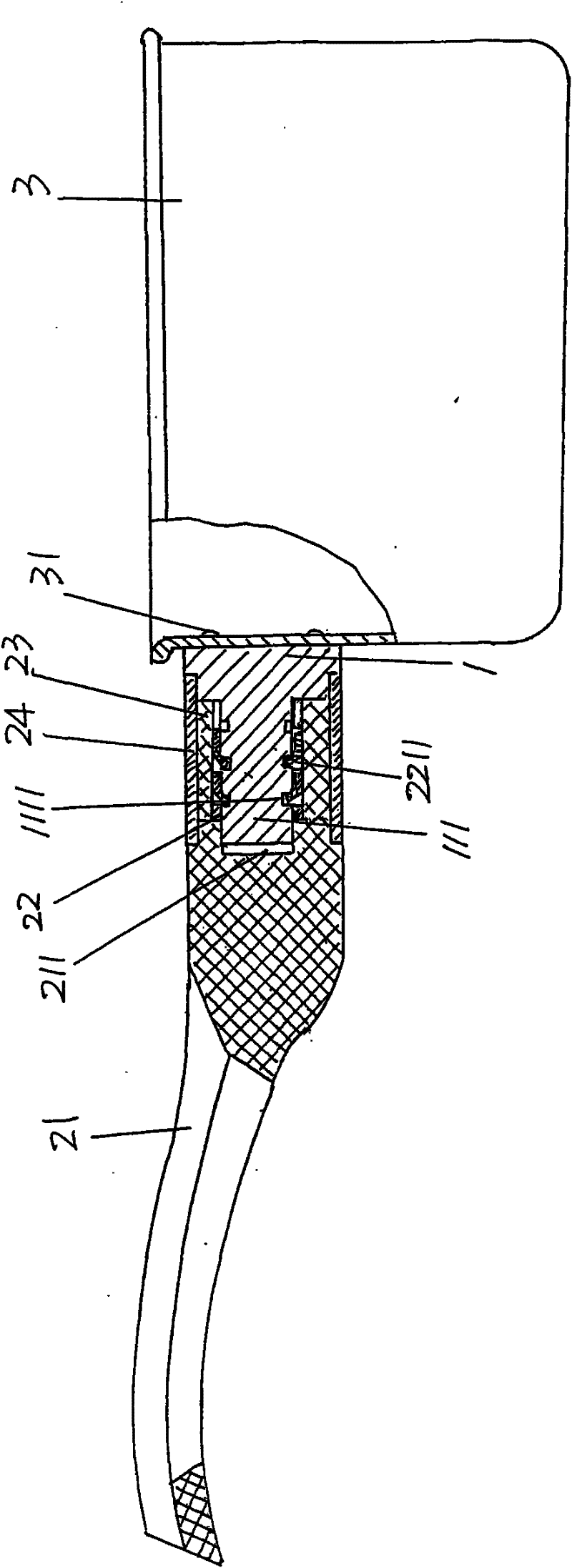
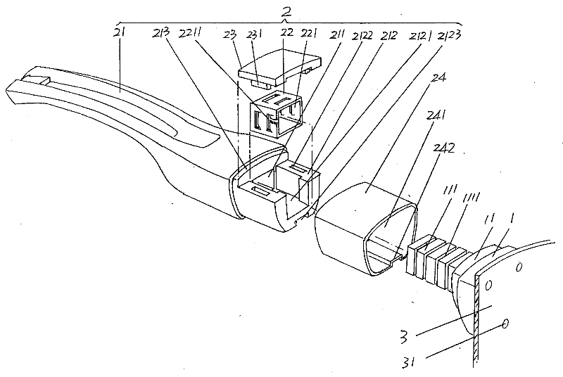
[0015] please see figure 1 and figure 2 , in order to make it easier for the public to understand, the applicant in figure 1 and figure 2 A pot body 3 is illustrated, but the applicant needs to explain that the shape of the pot body 3 is not limited by the illustrated shape. The handle seat 1 is used to fix the pot body 3, and is preferably formed by extruded aluminum, and is preferably riveted to fix th...


PUM


Abstract

The invention discloses an embedded fixed type lifting handle structure of a pot, and belongs to the field of cooking instruments. The lifting handle structure comprises a lifting handle seat and a lifting handle body, wherein an internal shrinkage step is formed on one side of the lifting handle seat; connecting blocks on which a group of barb grooves are formed are extended on the internal shrinkage step; the lifting handle body comprises a grip, a barb sleeve, a cover plate and a sheath; one end of the grip is provided with a connecting block compensation cavity; an adapter and a supporting step are extended at the one end of the grip; the adapter is provided with a barb sleeve cavity; the barb sleeve is provided with a connecting block accommodating cavity; the inner wall of the connecting block accommodating cavity is provided with barbs which are matched with the barb grooves; the cover plate is matched with the adapter; one end of the sheath is matched with the internal shrinkage step, and the other end of the sheath is matched with the supporting step; the adapter and the cover plate are positioned in a sheath cavity; and the connecting blocks are arranged in the connecting block accommodating cavity and also extend into the connecting block compensation cavity. The lifting handle structure has the advantages that: the mounting efficiency is improved and the working intensity of mounters is relieved; loosening is avoided during use so as to guarantee safety; a neatness effect is achieved; and any tool is not required to be used during assembly.

Description

technical field [0001] The invention belongs to the technical field of cooking utensils, and in particular relates to an embedded and fixed pot handle structure. Background technique [0002] The cooperation of the pot handle and the pot body in the prior art is realized in this way. First, the handle seat (also called the handle seat) is fixed to the pot body by riveting or welding or screws, and then the pot handle is fixed to the pot body with screws. The handle seat is fixed. That is to say, the pot handle and the pot body are fixed by fasteners twice successively. Fixing the pot handle and the handle seat is prone to the following shortcomings: first, the installation efficiency is low, and the labor intensity of the assembly workers is high; There is looseness or even falling off, so that the handle appears to swim and sway relative to the handle seat; the third is a potential safety hazard, because once the screw is suddenly loosened, the pot body and the handle are...

Claims


Application Information

Patent Timeline
Patent Type & Authority Patents(China)
IPC IPC(8): A47J45/06
Inventor 金钟文
Owner CHANGSHU KASMAIN
Learn More