
Mounting locating device for flushing spraying system of wet electrical dust precipitator

A technology of wet electrostatic precipitator and spray system, which is applied in the direction of external electrostatic separator, electrostatic separation, electrode cleaning, etc., which can solve the problems of long installation period, long distance of spray pipe, deformation of spray pipe, etc., to reduce installation Work strength, easy and fast installation, and the effect of reducing installation damage

Inactive Publication Date: 2016-08-03
ZHEJIANG TIANDI ENVIRONMENTAL PROTECTION TECH CO LTD
View PDF7 Cites 0 Cited by
  • Summary
  • Abstract
  • Description
  • Claims
  • Application Information

AI Technical Summary

Problems solved by technology

[0004] The components of the wet electrostatic precipitator are complicated, the installation requirements are more, and the installation period is longer
In order to ensure the coverage of the wet electric spray flushing system, the positioning of the spray system must be precise; the distance of the spray pipe is long, and the deviation of the supporting steel frame is large during installation and positioning, so it is necessary to have an adjustment structure to reduce the installation error; when installing the spray system, the wet The overall anti-corrosion of electricity has been completed, which limits the hot-fire construction of welding
After the wet power is put into operation, the thermal expansion of the frame causes the displacement of the spray pipe and the fixing device, resulting in the deformation of the spray pipe

Method used


Image

  • Mounting locating device for flushing spraying system of wet electrical dust precipitator
  • Mounting locating device for flushing spraying system of wet electrical dust precipitator
  • Mounting locating device for flushing spraying system of wet electrical dust precipitator

Examples


Embodiment Construction

[0022] The present invention will be further described below in conjunction with the examples. The description of the following examples is provided only to aid the understanding of the present invention. It should be pointed out that for those skilled in the art, without departing from the principle of the present invention, some improvements and modifications can be made to the present invention, and these improvements and modifications also fall within the protection scope of the claims of the present invention.

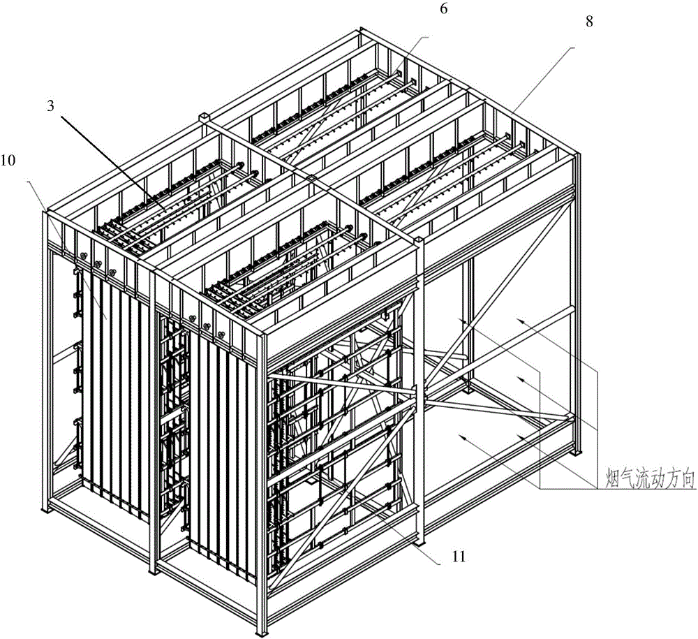
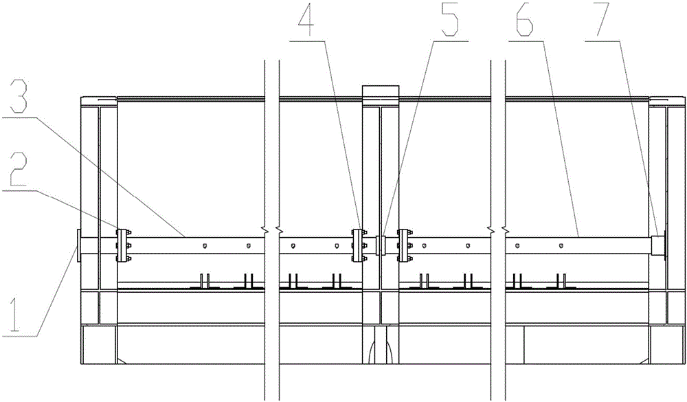
[0023] Such as Figure 1 to Figure 5 As shown, the installation and positioning device for the flushing and spraying system of the wet electrostatic precipitator includes the top side girder 8, the middle frame top beam 9, the limit sleeve 7, the sleeve 5 and the middle connecting pipe 4; The top side girders 8 are two respectively arranged on both sides of the middle frame top girder 9, the limit sleeve 7 is fixed on the top side girder 8 on one side, and the in...


PUM


Abstract

The invention relates to an installation and positioning device for a flushing and spraying system of a wet electrostatic precipitator, comprising a top side beam, a middle frame top beam, a limit casing, a casing and a middle connecting pipe; the top side beam is The two are respectively arranged on both sides of the top beam of the middle frame, the limit casing is fixed on the top side beam on one side, and the inlet pipe connection is arranged on the top side beam on the other side; the casing is arranged on the top beam of the middle frame , the middle connecting pipe is set on the casing and can move forward and backward; the front and rear ends of the middle connecting pipe are respectively connected to the front spray pipe and the rear spray pipe; the other end of the front spray pipe is connected to the inlet pipe, and the other end of the rear spray pipe is connected One end is connected with the limit sleeve. An installation and positioning device for a wet electric spray system: the spray pipe is installed in the upper part of the wet electric middle frame, the installation is simple, fast, firm and reliable; compared with other installation methods, the number of flange connections is reduced, and the installation work intensity is reduced.

Description

technical field [0001] The invention relates to the technical field of flue gas dust removal, in particular to an installation and positioning device for a flushing and spraying system of a wet electrostatic precipitator. Background technique [0002] Wet electrostatic precipitator is a kind of dust removal equipment used to deal with tiny dust and fine particles. As my country's requirements for flue gas and dust emissions from coal-fired units are increasing, wet electrostatic precipitators are gradually applied to the flue gas emission system; wet electricity can effectively remove fine particles and SO by improving dust removal efficiency. 3 and other pollutants to achieve ultra-low emission performance indicators. [0003] The spray system is also the biggest difference between the internal structure of wet and dry electrostatic precipitators. The wet electrostatic precipitator sprays and washes the anode plate with dedusting water through the spray system, so that th...

Claims


Application Information

Patent Timeline
Patent Type & Authority Applications(China)
IPC IPC(8): B03C3/16B03C3/78B03C3/34
CPCB03C3/16B03C3/34B03C3/78
Inventor 徐轶伦单新宇刘文榉陈瑶姬沈海涛钟莎刘志林
Owner ZHEJIANG TIANDI ENVIRONMENTAL PROTECTION TECH CO LTD
Learn More