Microchannel heat exchanger

A micro-channel heat exchanger and micro-channel technology, applied in evaporator/condenser, lighting and heating equipment, refrigeration components, etc., can solve the problem that the wall thickness of the micro-channel cannot meet the heat transfer requirements, and the problem of thermal resistance has not been solved. It is difficult to choose aluminum tube profiles and other issues

Inactive Publication Date: 2011-07-06
HANGZHOU SHENSHI ENERGY CONSERVATION TECH
View PDF9 Cites 11 Cited by
  • Summary
  • Abstract
  • Description
  • Claims
  • Application Information

AI Technical Summary

Problems solved by technology

But the above-mentioned three inventions have the following problems: 1. the heat exchange flat tube is an aluminum tube profile, and the size of the profile is a fixed value
There are restrictions on the selection of the hydraulic diameter of the microchannel, and it is difficult to select the aluminum tube profile after the structural optimization design
In addition, currently limited by the production technology of aluminum tube profiles, the wall thickness between micro-channels cannot meet the size required for heat transfer (very thin), so the micro-channel heat exchanger designed for aluminum tube profiles using flat tubes cannot Become the direction of microchannel heat exchanger technology
2. Brazing is used between the microchannels through which the refrigerant passes and the fins through which the air passes, and the resulting thermal resistance problem has not been resolved.
3. The above three applications are limited to bifurcated heat exchangers for heat exchange between refrigerant and air
However, in this application, the hydraulic diameters of the microchannels of the refrigerant and working liquid that affect the heat exchange efficiency of the heat exchanger are only limited to the micron level. Actually, according to theoretical reasoning and actual experiments, when the hydraulic diameter of the water side is too large Or too small, the forced convection heat transfer coefficient on the water side may not improve much, or the pressure loss will increase, and the heat transfer effect of the heat exchanger is not ideal

Method used


Image

  • Microchannel heat exchanger
  • Microchannel heat exchanger
  • Microchannel heat exchanger

Examples


Embodiment 1

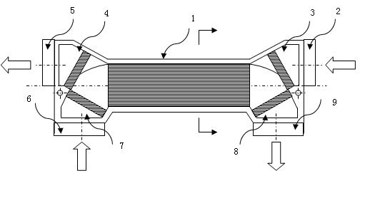
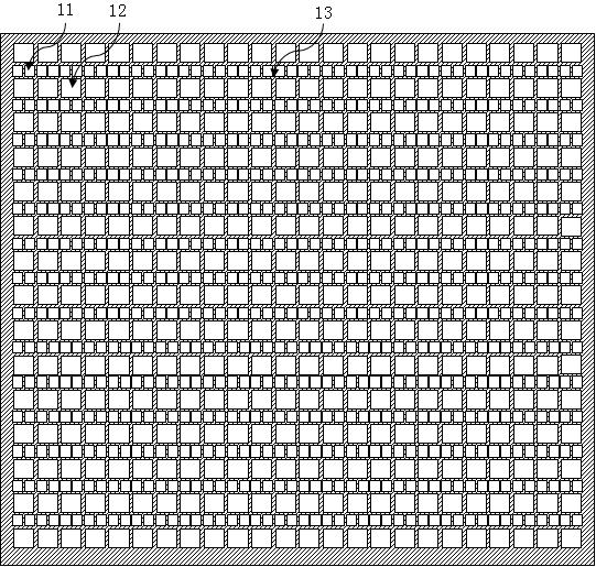
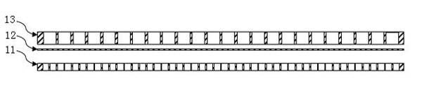
[0043] The structure of the microchannel heat exchanger of the present invention is as figure 1 , figure 2 As shown, it includes a heat exchange section 1, and the heat exchange section 1 is formed by stacking several unit layers, and each unit layer is a refrigerant layer 11, a separator layer 12, and a working fluid layer 13 in sequence, as shown in image 3 As shown; several microchannels are distributed on the refrigerant layer 11 and the working fluid layer 13 . The cross-section of each of the microchannels is square, and the sides of the micropore channels in the working fluid layer are flush with the side surfaces of the microchannels in the adjacent refrigerant layer. The ratio of the hydraulic diameter of the microchannels in the refrigerant layer 11 to the hydraulic diameter of the microchannels in the working fluid layer 13 is 1:2.

[0044] The microchannel heat exchanger also includes a working fluid inlet 2, a working fluid inlet supporting a rectifying porti...

Embodiment 2

[0059] The structure of the microchannel heat exchanger of this embodiment is roughly the same as that described in Example 1, the difference is that the cross section of each microchannel is circular, and the hydraulics of the microchannels of the refrigerant layer 11 The diameter is 0.0675mm. The hydraulic diameter of the microchannels in the working fluid layer 11 is 1.0125 mm. The refrigerant layer 11, the partition layer 12, and the working fluid layer 13 are made of copper. Heat exchangers using the above materials and sizes will slightly reduce the heat transfer performance, but can improve the flow characteristics of the working fluid, and it will be inconvenient in the selection of manufacturing materials. According to the physical properties of the refrigerant and working fluid used in the heat pump system, The overall performance is still within a reasonable range.

[0060] The method for manufacturing the microchannel heat exchange section 1 of the heat exchanger...

Embodiment 3

[0066] The structure of the microchannel heat exchanger of this embodiment is roughly the same as that described in Example 1, the difference is that the cross-section of each microchannel is elliptical, and the hydraulics of the microchannels of the refrigerant layer 11 The diameter is 0.5mm. The hydraulic diameter of the microchannels in the working fluid layer 11 is 0.125mm. The refrigerant layer 11, the separator layer 12, and the working fluid layer 13 are made of aluminum. Heat exchangers using the above materials and sizes will have improved heat transfer performance, increased flow pressure loss of the working fluid, and easy selection of manufacturing materials. According to the characteristics of the refrigerant and working fluid used in the heat pump system, The overall performance is still within a reasonable range.

[0067] The method for manufacturing the microchannel heat exchange section 1 of the heat exchanger comprises the following steps,

[0068] a. The ...


PUM


Abstract

The invention discloses a microchannel heat exchanger belonging to the technical field of heat transfer and heat exchange. The microchannel heat exchanger comprises a fluid channel, wherein a working fluid inlet (2) and a refrigerating medium outlet (9) are molded at one end of the fluid channel, and a working fluid outlet (5) and a refrigerating medium inlet (6) are molded at the other end. A heat exchange segment (1) is arranged in the fluid channel and is formed by alternately superposing a refrigerating medium layer (11) and a working fluid layer (13), the refrigerating medium layer (11) and the working fluid layer (13) are isolated through a baffle plate layer (12), and the refrigerating medium layer (11), the baffle plate layer (12) and the working fluid layer (13) are homogenously bonded. A plurality of parallel microchannels are respectively arranged on the refrigerating medium layer (11) and the working fluid layer (13), the heat exchange units are in homogenous structures, and the ratio of the hydraulic diameter of the microchannels of the refrigerating medium layer (11) to the hydraulic diameter of the microchannels of the working fluid layer (13) is 1:(0.25-15). In the invention, according to the use conditions of the heat pump system, a group of optimized hydraulic diameter values of the refrigerating medium microchannels and the working fluid microchannels are obtained through the heat transfer theory and fluid mechanics calculation and analysis. The heat transfer efficiency of microchannel heat exchanger is higher than that of the traditional heat exchange product.

Description

technical field [0001] The invention belongs to the technical field of heat transfer and heat exchange, and in particular relates to a microchannel heat exchanger. Background technique [0002] The use of heat pump systems such as air source heat pumps, heat pump water heaters, heat pump boilers and ground source heat pumps is inseparable from heat exchangers. At present, there are several types of heat exchangers, such as tube heat exchangers, plate heat exchangers, and microchannel heat exchangers. Among them, the tubular heat exchanger has the disadvantages of large volume, many consumables, and low heat exchange efficiency; under the same heat exchange capacity, the plate heat exchanger can reduce the weight and volume by more than half compared with the tubular heat exchanger, but the plate heat exchanger The heat exchanger also has problems such as small forced convection heat transfer coefficient, increased flow resistance caused by fins for enhancing heat transfer i...

Claims


Application Information

Patent Timeline
Patent Type & Authority Applications(China)
IPC IPC(8): F25B39/00
Inventor 王凱建
Owner HANGZHOU SHENSHI ENERGY CONSERVATION TECH
Why Eureka
Try Eureka