Check patentability & draft patents in minutes with Patsnap Eureka AI!

Method and device for measuring thermal resistance of diode

A measurement method and measurement device technology, applied in the field of diode thermal resistance measurement method and device, can solve the problems of unstable forward voltage and junction temperature, inaccurate test accuracy, unsatisfactory reproducibility, etc., and achieve simple and fast measurement, Ease of operation, simplification of procedures and equipment

Active Publication Date: 2011-07-06
HANGZHOU EVERFINE PHOTO E INFO
View PDF3 Cites 31 Cited by
  • Summary
  • Abstract
  • Description
  • Claims
  • Application Information

AI Technical Summary

Problems solved by technology

[0009] For the above measurement method, in the calculation of the temperature sensitive parameters, it is assumed that the change of the forward bias voltage of the diode and the junction temperature is linear, but in practice, different diodes, due to the difference in equipment technology and manufacturing process, their forward voltage and There is great instability in the junction temperature during the change process, and its linearity assumption needs to be verified; in addition, during the test process, it is assumed that the reference ambient temperature remains constant, but in the actual measurement process, due to the heat dissipation of the diode, The ambient temperature of its accessories will have a certain impact; in addition, in order to prevent the diode junction from cooling down during the current switching process, the current switching time is required to be extremely short, generally within a few microseconds, which will have higher requirements for the measuring equipment. And there is a lot of instability, the reproducibility is not ideal, and the test accuracy is not accurate enough

Method used


Image

  • Method and device for measuring thermal resistance of diode
  • Method and device for measuring thermal resistance of diode
  • Method and device for measuring thermal resistance of diode

Examples


Embodiment 1

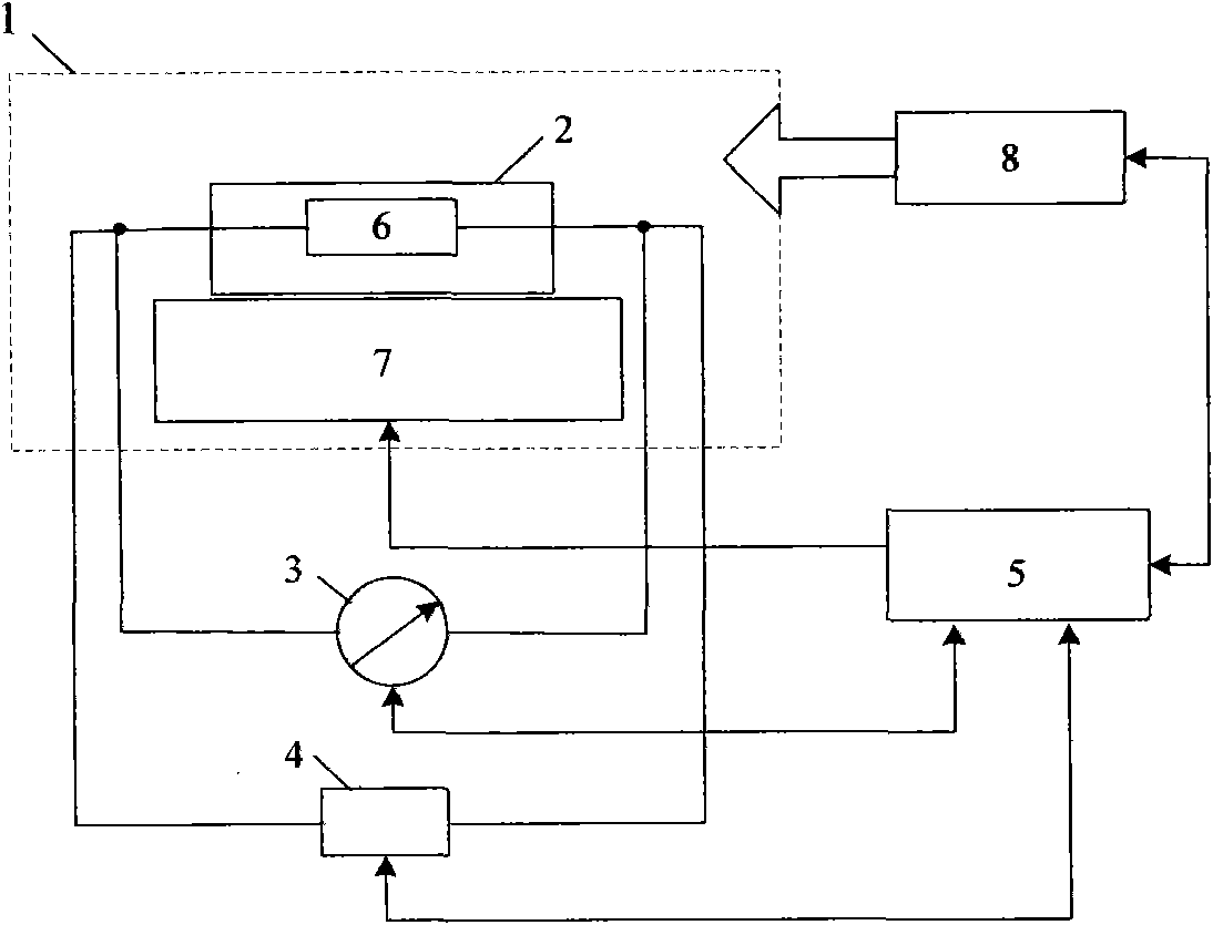
[0037] Attached below image 3 And embodiment, the present invention is described further.

[0038] Such as image 3 As shown, a diode thermal resistance measurement device includes a temperature control device 1, a test platform 2, a current source 3, a voltage acquisition device 4, and a control unit 5. The test platform 2 is placed in the temperature control device 1, and the measured diode 6 and The test platform 2 is in good contact and electrically connected with the current source 3 and the voltage acquisition device 4 , and the temperature control device 1 , the current source 3 and the voltage acquisition device 4 are all electrically connected with the control unit 5 .

[0039] The measured diode described in this embodiment is an ordinary diode (not emitting light), and the measured diode is measured by the measuring method and device of the present invention, and the measuring steps are as follows:

[0040] a) The control unit 5 controls the temperature control d...

Embodiment 2

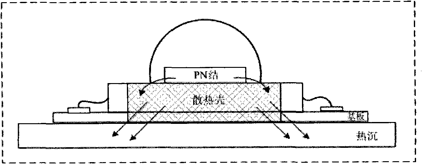
[0046] As shown in FIG. 5 , the tested diode 6 described in this embodiment is a light emitting diode. The method and device for measuring the thermal resistance of LEDs in this embodiment are similar to those in Embodiment 1, but due to the luminous power of the LEDs, the calculation of the electric power that causes the junction temperature of the diodes to rise is different from that in Embodiment 1. In addition to the device described in Example 1, the diode thermal resistance measurement device also includes a photometric measurement unit 9, which is electrically connected to the control unit 5, and is used for measuring the luminous power of the light-emitting diode.

[0047] Adopt measurement method and device of the present invention to measure diode under test, its measurement steps are as follows:

[0048] a) The control unit 5 controls the temperature control device 1 to control the temperature of the test platform 2 and the tested diode 6 to T 1 value, after reach...


PUM


Abstract

The invention discloses a method and a device for measuring the thermal resistance of a diode. The method comprises the steps of: controlling the temperature at a PN junction of a tested diode through a temperature control technology so as to obtain the difference between the temperature at the junction of the tested diode and the external reference environment temperature (or the temperature at a reference point of a heat dissipation channel) under stable condition; and measuring an input electric power causing the rising of the temperature at the junction of the tested diode so that the thermal resistance of the tested diode can be computed. The device adopts a heating / cooling unit and a synchronous rapid sampling unit; and when the rising of the temperature at the junction of the tested diode can be ignored under a set higher temperature value, voltage amplitudes at two ends of the tested diode can be rapidly measured. Through the method and the device for measuring the thermal resistance of the diode, the precise measurement of the thermal resistance of the diode can be realized, the measurement is simple and rapid, the operation is convenient, and the stability is good.

Description

【Technical field】 [0001] The invention belongs to the field of semiconductor device measurement, in particular to a diode thermal resistance measurement method and device. 【Background technique】 [0002] The diode will generate a lot of heat during the working process, causing the temperature at the PN junction to rise, thereby affecting the working performance and service life of the diode. Therefore, in the structural design of the diode, its heat dissipation property is an important factor that must be considered. The thermal resistance of a diode indicates the ability of the diode to dissipate heat. Accurate measurement of diode thermal resistance has important reference significance for improving diode packaging and heat dissipation design, and will help diodes achieve rapid development and wider application. [0003] According to the internal structure of the packaged diode, when heat is generated inside the device, the heat diffuses to the external environment throug...

Claims


Application Information

Patent Timeline
IPC IPC(8): G01R31/26
Inventor 潘建根
Owner HANGZHOU EVERFINE PHOTO E INFO
Features
  • R&D
  • Intellectual Property
  • Life Sciences
  • Materials
  • Tech Scout
  • Unparalleled Data Quality
  • Higher Quality Content
  • 60% Fewer Hallucinations
Learn More