Eureka AIR delivers breakthrough ideas for toughest innovation challenges, trusted by R&D personnel around the world.

Long-life active electronic tag

A technology of electronic tags and capacitors, applied in the field of low-power active electronic tags, which can solve the problems of battery capacity waste, capacity waste, and short service life

Inactive Publication Date: 2011-07-06
上海锐帆信息科技有限公司
View PDF2 Cites 3 Cited by
  • Summary
  • Abstract
  • Description
  • Claims
  • Application Information

AI Technical Summary

Problems solved by technology

[0003] In order to overcome the waste of battery capacity and short service life of traditional active electronic tags, the present invention proposes a method for implementing long-life active electronic tags, the specific content of which includes abandoning the design method of traditional active electronic tags, A capacitive energy storage unit is added between the original power supply system of the active electronic tag and the working circuit, so that the active electronic tag power system composed of lithium batteries does not directly provide power to the active electronic tag working circuit, but first supplies power to the active electronic tag working circuit. The capacitive energy storage unit supplies power, and then the capacitive energy storage unit directly supplies current to the working circuit of the active electronic label
Such a design mechanism makes the lithium battery avoid the use of high current and intermittent working mechanism that is very harmful to cooperate with the working mode of the active electronic tag, and can protect the lithium battery to the greatest extent and exert all the power of the lithium battery, while the capacitance energy The working mechanism of the storage unit needs to be continuously charged and discharged, which can just match the working mode of the active electronic tag, which completely solves the defects of capacity waste and short service life caused by the use of lithium batteries in the active electronic tag.

Method used


Image

  • Long-life active electronic tag
  • Long-life active electronic tag
  • Long-life active electronic tag

Examples


Embodiment Construction

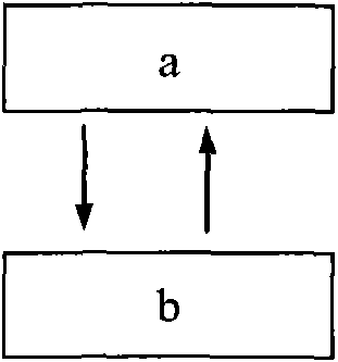
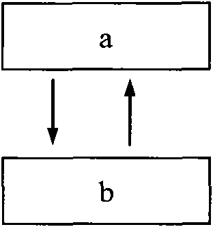
[0015] Under normal circumstances, 6 is in state a, the lithium battery automatically charges the capacitive energy storage unit with a small current and in a stable manner, and the capacitive energy storage unit provides electric energy for the active electronic tag working circuit in a micro-current discharge;

[0016] After the counter counts to a certain cycle time T1, trigger 2 to enter state b;

[0017] The time length of state b is T2, and the task of sending the ID identification information of the tag is completed within the T2 period. The capacitive energy storage unit provides electric energy to the active electronic tag working circuit in a large current discharge, and the time period of the large current discharge is T2. At this time, the lithium battery is still automatically charged to the capacitive energy storage unit with a small current and in a stable manner, and after T2 ends, 6 returns to state a;

[0018] Re-enter the next round of working state cycle.


PUM


Abstract

The invention provides a long-life active electronic tag. In order to overcome the defects of the conventional active electronic tag, such as battery capacity waste and short service life, the invention provides a long-life active electronic tag by combining an active wireless RF (radio frequency) recognition technology with ultra-low power consumption and a capacitor energy storage technology. The power supply system of the active electronic tag consists of a lithium battery and a capacitor energy storage unit, and has such a work mode that the lithium battery supplies power to the capacitor energy storage unit in a continuous small-current manner, and the capacitor energy storage unit supplies power to the work circuit of the active electronic tag in a discharge mode of combining large current and micro-current. The wireless RF microprocessing unit and RF circuit of the active electronic tag are of ultra-low power consumption designs, and use large current only in a small time window during work to transmit the inherent ID (identify) information in the wireless manner; and then the microprocessing unit and the RF circuit enter a dormant state using the micro-current.

Description

Technical field [0001] The invention relates to a realization method suitable for low power consumption active electronic tags. Background technique [0002] The People's Republic of China patents 200420037164.3 "Container electronic label device" and 200810039151.2 "Active RFID radio frequency identification label and reader for container electronic seals" have announced two design methods for active electronic tags, but they all have the following disadvantages: Due to the ultra-low self-discharge characteristics of lithium batteries, active electronic tags use lithium batteries as internal power sources to work. Due to the working principle of lithium battery discharge, the best way to work is to release current smoothly and stably, so that lithium batteries can work The service life reaches the maximum and the power release is the most complete. However, the working mode of the active electronic tag is to transmit information periodically. After a period of time, it wil...

Claims


Application Information

Patent Timeline
IPC IPC(8): G06K19/07H02J15/00
Inventor 欧海涛徐双赵明
Owner 上海锐帆信息科技有限公司
Why Eureka
Eureka Blog
Learn More