Insulation protection barrier for partitioning dynamic batteries

A technology for insulation protection and power batteries, applied in the direction of battery pack parts, circuits, electrical components, etc., can solve problems such as heat accumulation, battery casing leakage, battery short circuit, etc., to improve heat dissipation performance, ensure insulation, and avoid insulation The effect of failure

Active Publication Date: 2013-03-06
BAILE ELECTROTHERMIC ELECTRIC APPLIANCE JIANGSU
View PDF0 Cites 0 Cited by
  • Summary
  • Abstract
  • Description
  • Claims
  • Application Information

AI Technical Summary

Problems solved by technology

[0002] The current power battery will not only radiate heat outside during use, if the heat cannot be taken away quickly, it will cause heat to accumulate in the battery box, and the temperature will gradually rise, causing the battery to fail or even the danger of fire and explosion. Therefore, it is necessary to ensure that the battery The ventilation and heat dissipation of the power supply system, and after long-term use of the power supply system, occasionally there will be extreme phenomena of some battery safety valves spraying electrolyte or battery shell leakage. Due to the strong conductivity and corrosion of the electrolyte, the electrolyte that flows out is very easy. The conduction of the metal shell or the conduction of the battery and the box will cause a great safety hazard to the power system. In severe cases, it will cause the battery to short-circuit and cause fire and explosion. Therefore, the insulation performance of the power battery must be ensured during use.

Method used


Image

  • Insulation protection barrier for partitioning dynamic batteries
  • Insulation protection barrier for partitioning dynamic batteries

Examples


Embodiment Construction

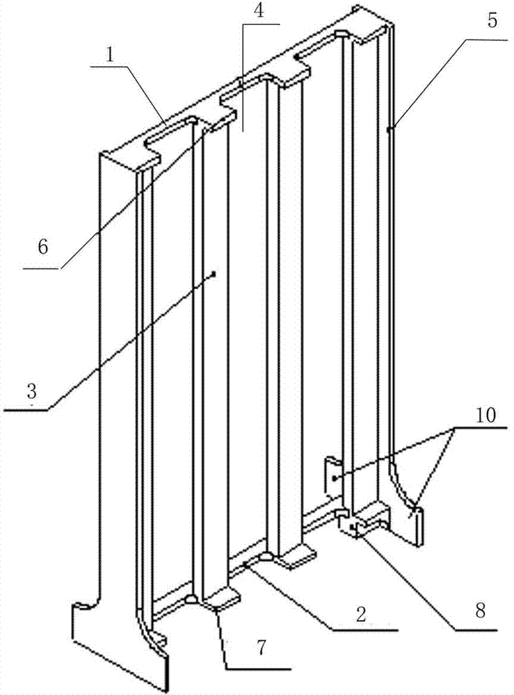
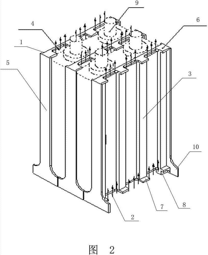
[0009] exist figure 1 Among them, the present invention is an insulating and protective barrier separating power batteries, which mainly includes an upper connecting beam 1, a lower connecting beam 2, and several parallel and vertically arranged grid bars 3. This embodiment includes 4 grid bars 3. The gaps provided between the grid bars 3 form air ducts 4, the upper connecting beam 1 and the lower connecting beam 2 are respectively horizontally arranged on the top and bottom of each grid bar 3, and the upper connecting beam 1 and the lower connecting beam 2 connect each The grid bars 3 are connected in series to form a grid body, the grid body is made of glass fiber flame-retardant plastic, and the outer surfaces of the grid bars 1 on both sides of the grid body are connected with side limit blocks 5, and each side limit block 5 The bottom extends to both sides to form a windshield 10, the width of the windshield 10 is greater than the width of the side limit block 5, the widt...


PUM


Abstract

The invention discloses an insulation protection barrier for partitioning dynamic batteries. An air duct (4) is formed by a gap arranged among grid bars (3); an upper connecting beam (1) and a lower connecting beam (2) are respectively horizontally arranged at the top and the bottom of each of the grid bars (3); the upper connecting beams (1) and the lower connecting beams (2) connect the grid bars (3) in series to form a barrier body; side edge limiting blocks (5) are connected to the outer surfaces of the grid bars (3) at two sides of the barrier body; the widths of the side edge limiting blocks (5) are larger than those of the grid bars (3); an upper limiting block (6) horizontally extends from a position on the upper connecting beam (1) corresponding to the grid bars (3); a lower limiting block (7) horizontally extends from a position on the lower connecting beam (2) corresponding to the grid bars (3); the upper limiting block (6), the lower limiting block (7) and the two side edge limiting blocks (5) are enclosed to form a battery limiting part; and a foot margin (8) is arranged at the bottom of the lower connecting beam (2).

Description

technical field [0001] The invention relates to an insulating protective barrier for separating power batteries. Background technique [0002] The current power battery will not only radiate heat outside during use, if the heat cannot be taken away quickly, it will cause heat to accumulate in the battery box, and the temperature will gradually rise, causing the battery to fail or even the danger of fire and explosion. Therefore, it is necessary to ensure that the battery The ventilation and heat dissipation of the power supply system, and after long-term use of the power supply system, occasionally there will be extreme phenomena of some battery safety valves spraying electrolyte or battery shell leakage. Due to the strong conductivity and corrosion of the electrolyte, the electrolyte that flows out is very easy. The conduction of the metal shell or the conduction of the battery and the box will cause a great safety hazard to the power system. In severe cases, it will cause ...

Claims


Application Information

Patent Timeline
Patent Type & Authority Patents(China)
IPC IPC(8): H01M2/18H01M2/16
CPCY02E60/12Y02E60/10
Inventor 孔令兵曹广勇袁婕
Owner BAILE ELECTROTHERMIC ELECTRIC APPLIANCE JIANGSU
Why Eureka
Try Eureka