Dual-frequency antenna

A dual-band antenna and antenna technology, which is applied in directions such as antennas, antenna supports/installation devices, and devices that enable the antennas to work in different bands at the same time, can solve problems such as low elevation gain, achieve good grounding, no need to cut corners, and is easy to use. The effect of debugging

Inactive Publication Date: 2011-07-06
HARXON CORP
View PDF1 Cites 7 Cited by
  • Summary
  • Abstract
  • Description
  • Claims
  • Application Information

AI Technical Summary

Problems solved by technology

[0009] 4. Low

Method used


Image

  • Dual-frequency antenna
  • Dual-frequency antenna
  • Dual-frequency antenna

Examples


Embodiment Construction

[0029] The technical solutions of the present invention will be further described below in conjunction with the accompanying drawings and specific embodiments.

[0030] It should be understood that the specific embodiments described here are only used to explain the present invention, not to limit the present invention.

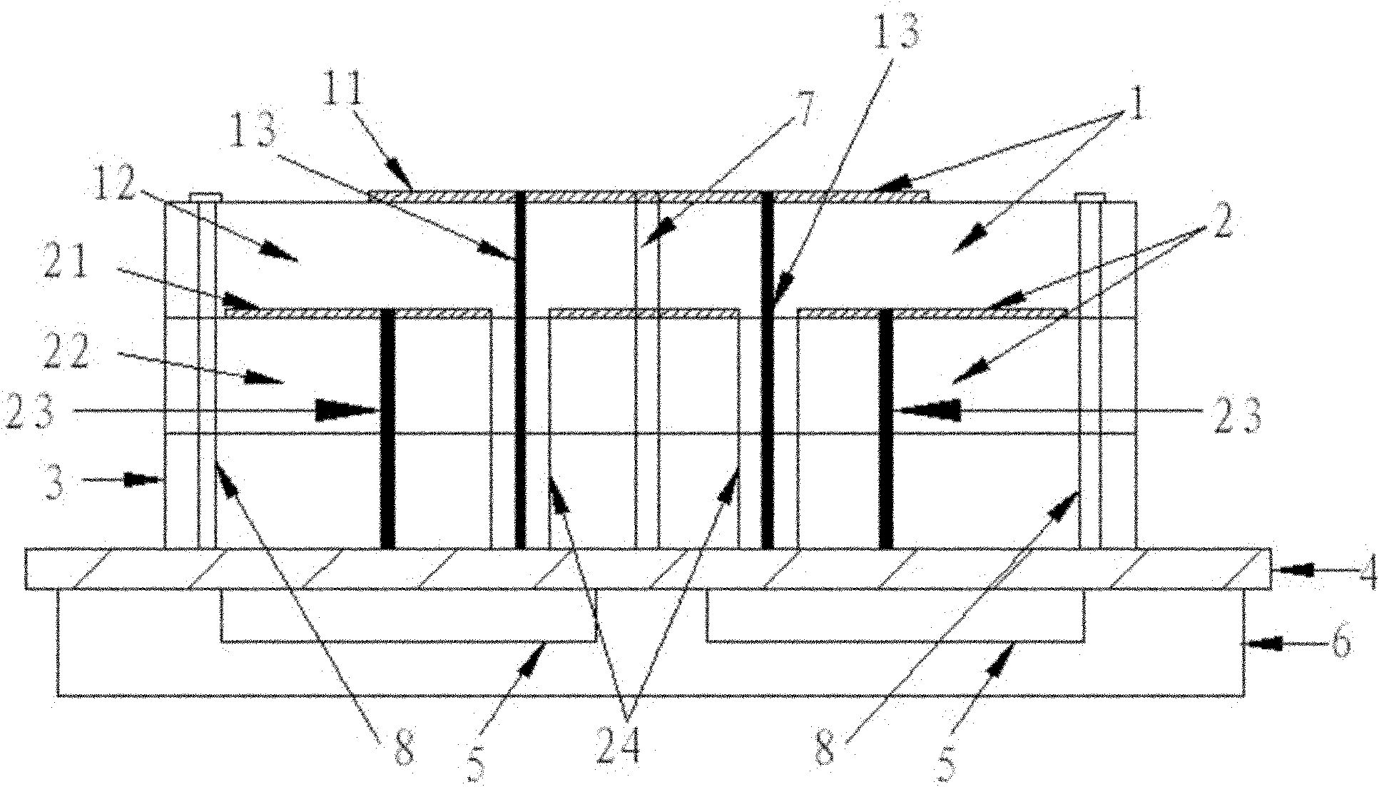
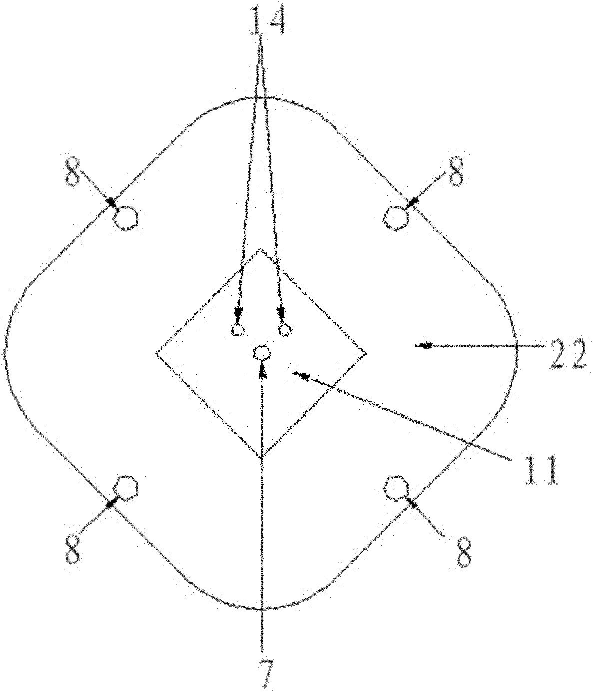
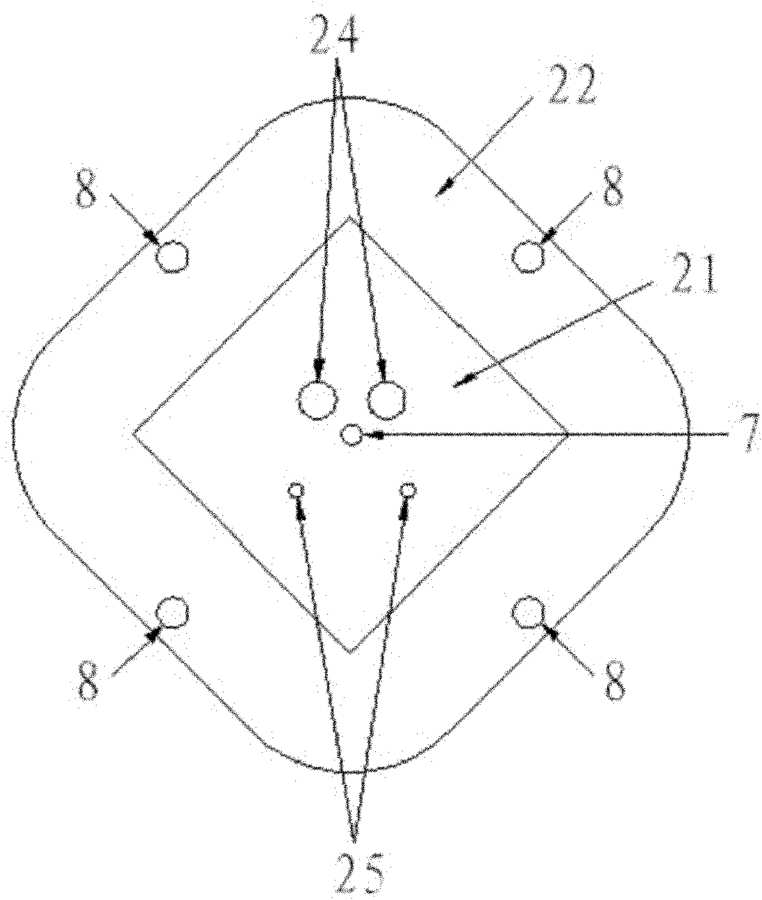
[0031] Such as figure 1 As shown, it is a cross-section schematic diagram of a preferred embodiment of the dual-frequency antenna of the present invention; this embodiment includes an upper layer microstrip antenna 1, a lower layer microstrip antenna 2, a dielectric layer 3, a reflector 4, and a phase-shifting feed at the back of the reflector 4 The electrical network 5 and the shielding box 6 located directly below the back of the reflector 4; in the figure, 11 is the radiation patch of the upper microstrip antenna 1, 12 is the dielectric substrate of the upper microstrip antenna 1, and 13 is the upper microstrip antenna 1 21 is the radiation patch of the l...


PUM


Abstract

The invention relates to a dual-frequency antenna. The dual-frequency antenna comprises an upper microstrip antenna, a lower microstrip antenna, a reflector plate and two phase shifting feed networks, wherein the upper microstrip antenna and the lower microstrip antenna are fixed to the front surface of the reflector plate by bolts after being overlapped; the phase shifting feed networks are positioned on the back surface of the reflector plate; and both the upper microstrip antenna and the lower microstrip antenna feed through a dual-fed pin. The dual-frequency antenna not only is easy to realize, but also has a small volume, a good axial ratio bandwidth and a low elevation gain.

Description

technical field [0001] The invention relates to the field of antennas, in particular to a dual-frequency antenna. Background technique [0002] With the rapid development of satellite navigation technology and its wide application in various fields, the antenna performance of the handheld receiving device in the high-precision measurement satellite navigation and positioning system has also put forward higher and higher requirements, mainly in the following aspects: [0003] 1. Good circular polarization performance [0004] In satellite communication, because of the small attenuation of circularly polarized waves in rain and snow, and their strong ability to penetrate the ionosphere, they are not affected by the Faraday effect of the magnetic field at the two poles of the earth. Satellite communications generally use circularly polarized signals. Therefore, the antenna should also work in a good circular polarization state to better match the system. [0005] 2. Can accep...

Claims


Application Information

Patent Timeline
IPC IPC(8): H01Q5/00H01Q1/24H03H7/18
Inventor 黄毅王春华
Owner HARXON CORP
Why Eureka
Try Eureka