Carrier management method in multi-carrier system and evolved node B (eNB)

An evolved base station and carrier management technology, which is applied in the field of wireless communication and can solve problems such as wasteful occupation of public resources, impact on public resource allocation, and system capacity impact.

Inactive Publication Date: 2014-07-02
ZTE CORP
View PDF3 Cites 0 Cited by
  • Summary
  • Abstract
  • Description
  • Claims
  • Application Information

AI Technical Summary

Problems solved by technology

Although this solution increases the flexibility of carrier management, the disadvantage is that some of the carrier configuration parameters are public configuration parameters that rarely change, and some are configuration parameters related to the occupation of control channel resources and uplink reference signal resources ( For example, channel quality indicator configuration parameters, scheduling request configuration parameters, and uplink reference signal configuration parameters), the resources configured by these parameters are common resources shared by UEs. When the eNB allocates these common resources to a certain UE, it will inevitably affect other UE common resource allocation
If the eNB sends all the configuration information of the target carrier to the UE, but does not activate the carrier for a long time, it will cause the UE to wastefully occupy the public resources of the target carrier and affect the system capacity.

Method used


Image

  • Carrier management method in multi-carrier system and evolved node B (eNB)
  • Carrier management method in multi-carrier system and evolved node B (eNB)
  • Carrier management method in multi-carrier system and evolved node B (eNB)

Examples


Embodiment 1

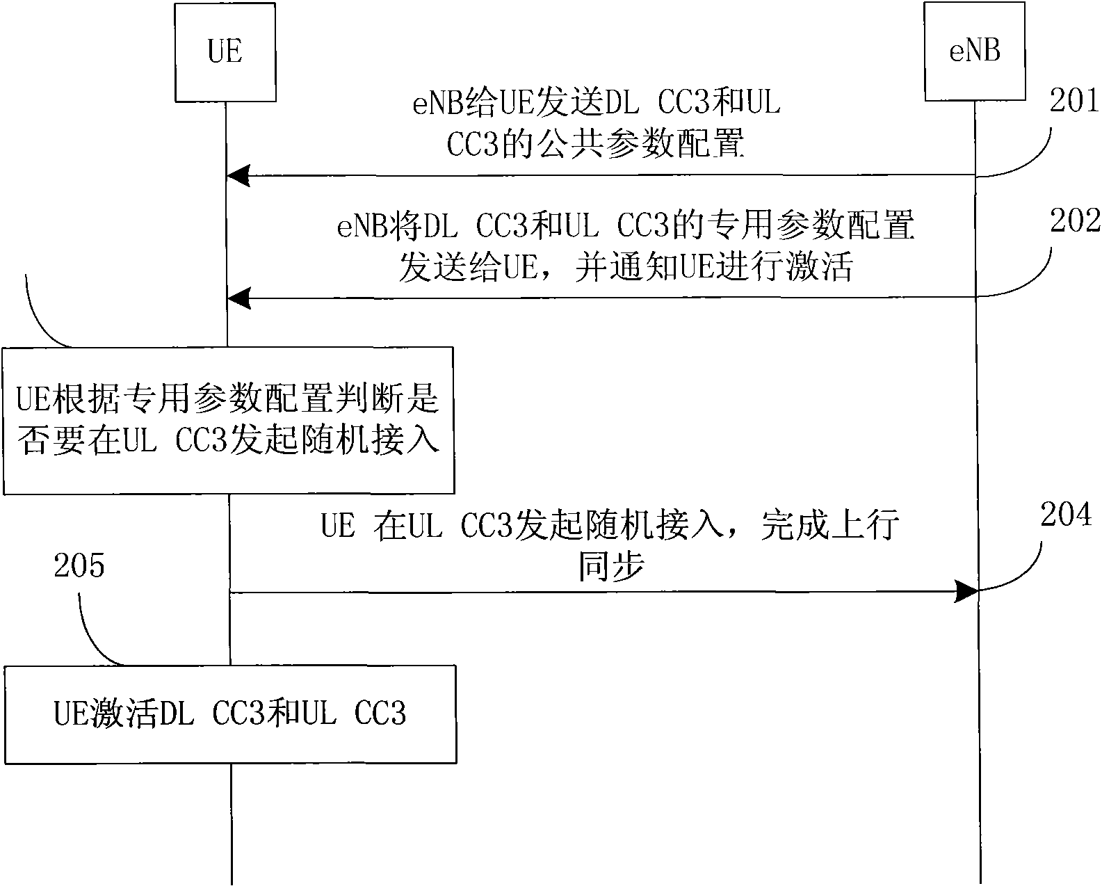
[0212] Assume that the UE and eNB have established an RRC connection, and the eNB configures two pairs of uplink and downlink carriers for the UE. The downlink carriers are DL CC1 (Downlink Component Carrier, downlink component carrier) and DLCC2, and the corresponding uplink carriers are UL CC1 (Uplink Component Carrier, uplink component carrier) and UL CC2.

[0213] It is assumed that the eNB needs to add a pair of uplink and downlink carriers for the UE due to the increase of traffic demanded by the UE, which are DL CC3 and UL CC3. DL CC3 is not synchronized with DL CC1 and DL CC2. UE needs to initiate random access on UL CC3 to obtain uplink synchronization. This information is included in the dedicated parameter configuration of DL CC3 and UL CC3.

[0214] The carrier management in this embodiment adopts the carrier management method 1 described in the summary of the invention, and the process of adding a carrier for the UE in this embodiment is as follows figure 2 As s...

Embodiment 2

[0221] It is assumed that the UE and the eNB have established an RRC connection, and the eNB configures two pairs of uplink and downlink carriers for the UE. The downlink carriers are DL CC1 and DL CC2, and the corresponding uplink carriers are UL CC1 and UL CC2 respectively.

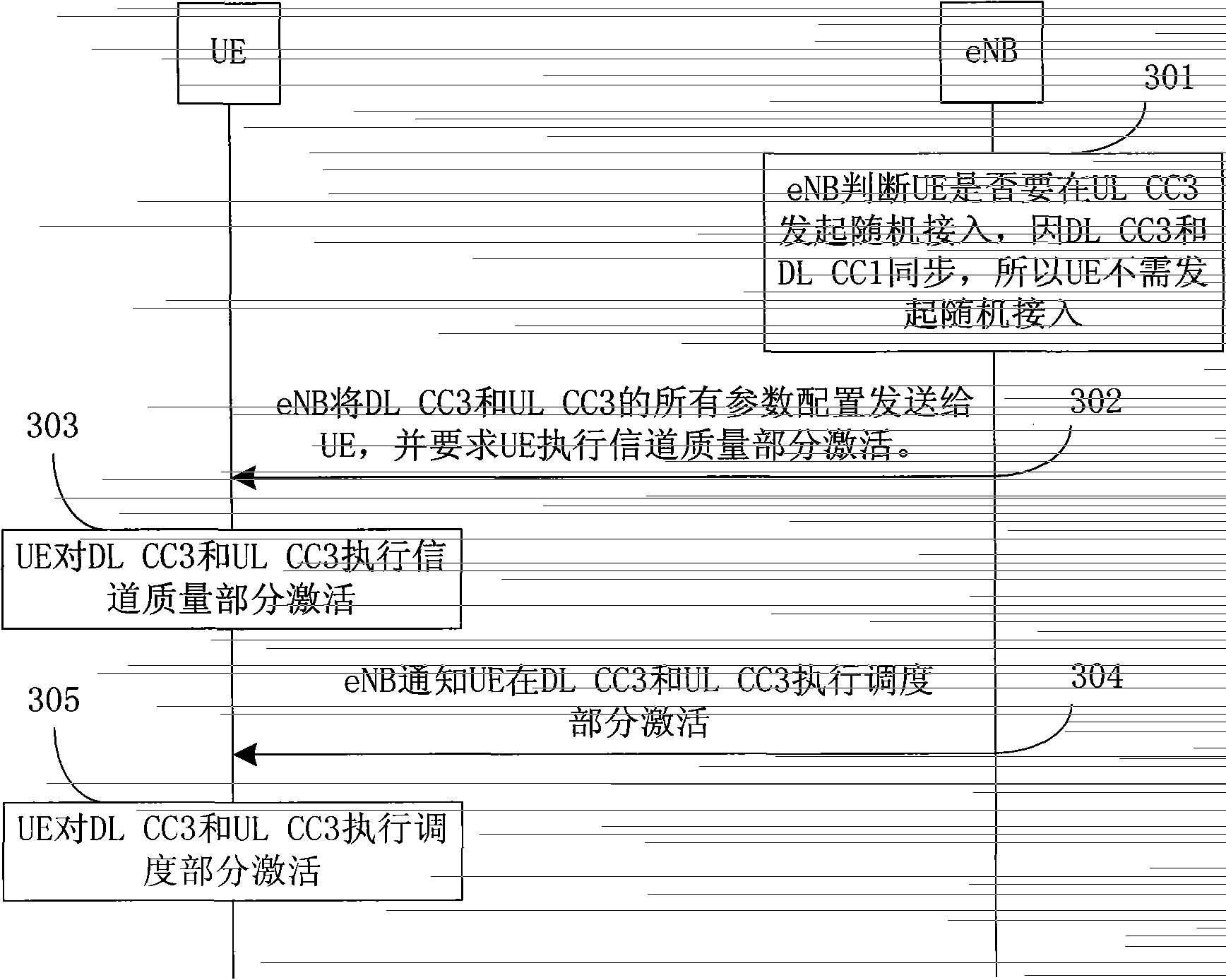
[0222] Assuming that the eNB needs to add a pair of uplink and downlink carriers for the UE due to the heavy load of the existing carrier, let them be DL CC3 and UL CC3. DL CC3 and DL CC1 are synchronized, and this information is included in the dedicated parameter configuration of DL CC3 and UL CC3.

[0223] The carrier management in this embodiment adopts the carrier management method 2 described in the summary of the invention, and the process of adding a carrier for the UE in this embodiment is as follows image 3 As shown, the steps are detailed as follows:

[0224] Step 301: The eNB judges whether the UE will initiate random access on UL CC3, because DL CC3 and DL CC1 are synchronized, so the UE ...

Embodiment 3

[0230] It is assumed that the UE and the eNB have established an RRC connection, and the eNB configures two pairs of uplink and downlink carriers for the UE. The downlink carriers are DL CC1 and DL CC2, and the corresponding uplink carriers are UL CC1 and UL CC2 respectively.

[0231] This embodiment gives an example of the eNB adjusting the activation and deactivation of the carrier in real time according to the change of the UE traffic. In this embodiment, the parameters are not released, so that when the eNB needs to use the target carrier again, the carrier can be reactivated quickly, which greatly reduces the scheduling delay and signaling overhead. This is a part of the carrier management method described in the present invention. An example of flexible use. There are similar applications in other embodiments.

[0232] Assume that the eNB needs to reduce a pair of uplink and downlink carriers for the UE due to the decrease in the traffic demand of the UE, which are DL C...


PUM


Abstract

A method for carrier management and an evolved Node-B (eNB) in multi-carrier system are provided in the present invention, and the method for carrier management in multi-carrier system includes: all parameters of a carrier are divided into public parameters and private parameters; and during said carrier parameter configuration process for a user equipment (UE), the evolved Node-B configures carrier parameters according to the dividing types in batches. Said carrier management method of present invention, by the improvement on the carrier increase and removal process, well solves the problem of implementation complexity in the carrier increase and removal process, reduces the system overhead, improves the flexibility of the carrier management, and saves UE power consumption.

Description

technical field [0001] The invention relates to the technical field of wireless communication, in particular to a carrier management method and an evolved base station in a multi-carrier system. Background technique [0002] In the Evolved Universal Terrestrial Radio Access Network (E-UTRAN for short) of the third-generation mobile communication Long Term Evolution (LTE for short) system, the uplink data passes through the physical uplink Physical Uplink Shared Channel (PUSCH for short) transmission. An evolved base station (Evolved NodeB, eNB for short) allocates uplink radio resources to each user terminal (User Equipment, UE for short). The access technology adopted by E-UTRAN is OFDM (Orthogonal Frequency Division Multiplexing) technology. Compared with the second-generation mobile communication system, the radio resource management of E-UTRAN system has a large bandwidth and multiple time processes. Its wireless resources appear in two dimensions of time and frequency...

Claims


Application Information

Patent Timeline
Patent Type & Authority Patents(China)
IPC IPC(8): H04L27/26H04W72/04H04W88/08H04B7/26
CPCH04W72/04H04L5/0007H04L5/0037H04L5/0064Y02D30/70
Inventor 戴谦施小娟
Owner ZTE CORP
Why Eureka
Try Eureka