Profile geothermal floor

A geothermal floor and profile technology, applied in the field of building decoration materials, can solve the problems of low heat conduction efficiency, short heat conduction path, complex manufacturing process, etc., and achieve high heat conduction efficiency, short heat conduction path, and good thermal stability.

Inactive Publication Date: 2011-07-13
李增清
View PDF1 Cites 5 Cited by
  • Summary
  • Abstract
  • Description
  • Claims
  • Application Information

AI Technical Summary

Problems solved by technology

[0004] The purpose of the present invention is to provide a profiled geothermal floor with short heat conduction path, high heat conduction efficiency, and heat can be quickly transferred to the floor surface, which solves the problem of long heat conduction path, low heat conduction efficiency and difficulty in rapid heat transfer in the prior art to the floor surface, complex manufacturing process, etc.

Method used


Image

  • Profile geothermal floor
  • Profile geothermal floor
  • Profile geothermal floor

Examples


Embodiment 1

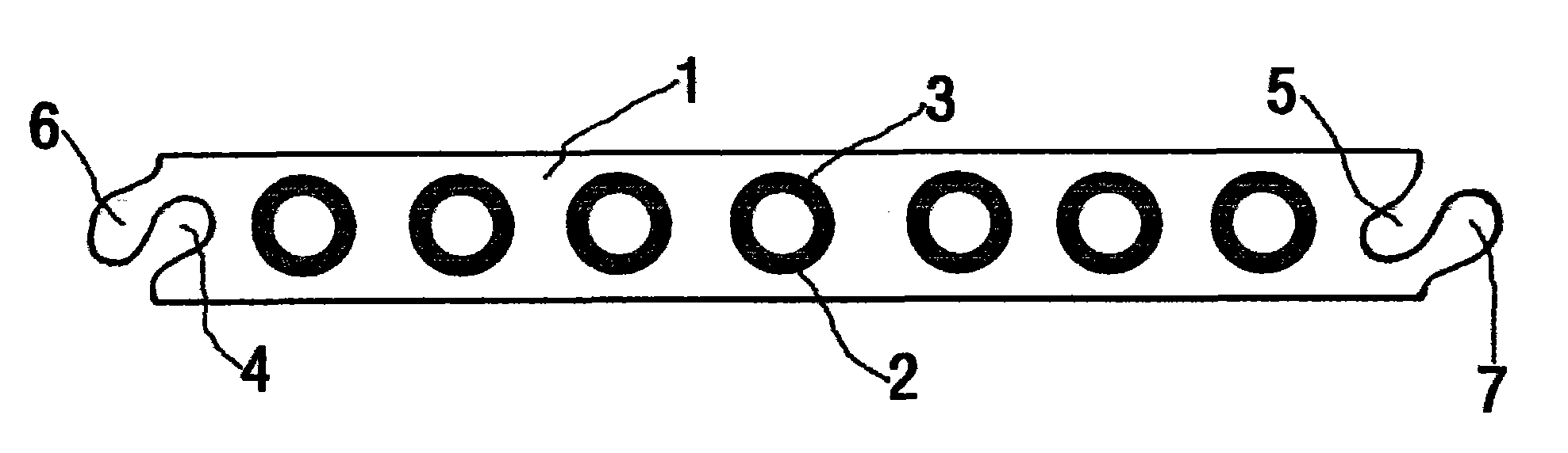
[0028] Embodiment 1: as figure 1 As shown, the interior of the floor body 1 is provided with seven through holes 2 that pass through the two ends of the floor body. The heat conduction medium 3, the outer surface of the heat conduction medium 3 is in contact with the inner wall of the through hole 2, the heat conduction medium 3 has a circular hollow tubular structure, and the through hole 2 has a corresponding circular structure. The opposite sides of the floor body are centrally symmetrical, and the first side of the floor body forms a first slot 4 extending along the first side of the floor body and having a cross-section such that the inner end is larger and the outer end is smaller. The second side of the opposite floor body forms a second slot 5 that extends along the second side of the floor body and has a large inner end and a small outer end in cross section. The upper wall of the first slot 4 is formed along the bottom of the floor body. The first clip strip 6 whose...

Embodiment 2

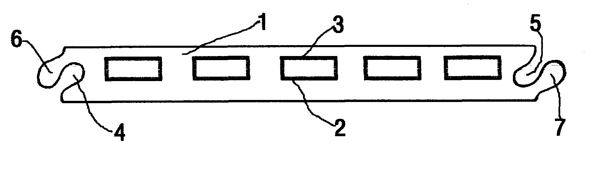
[0029] Embodiment 2: as figure 2 As shown, the interior of the floor body 1 is provided with five through holes 2 passing through both ends of the floor body. The heat conduction medium 3, the outer surface of the heat conduction medium 3 is in contact with the inner wall of the through hole 2, the heat conduction medium 3 has a rectangular hollow tubular structure, and the through hole 2 has a corresponding rectangular structure. The opposite sides of the floor body are centrally symmetrical, and the first side of the floor body forms a first slot 4 extending along the first side of the floor body and having a cross-section such that the inner end is larger and the outer end is smaller. The second side of the opposite floor body forms a second slot 5 that extends along the second side of the floor body and has a large inner end and a small outer end in cross section. The upper wall of the first slot 4 is formed along the bottom of the floor body. The first clip strip 6 whos...

Embodiment 3

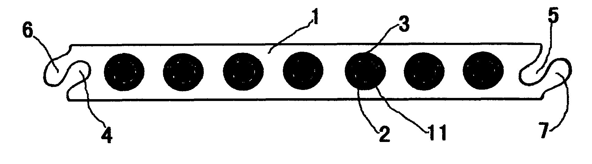
[0030] Embodiment 3: as image 3 As shown, the interior of the floor body 1 is provided with seven through holes 2 that pass through the two ends of the floor body. The heat conduction medium 3, the outer surface of the heat conduction medium 3 is in contact with the inner wall of the through hole 2, the heat conduction medium 3 has a circular hollow tubular structure, the through hole 2 has a corresponding circular structure, and the heat conduction medium 3 of each hollow tubular structure is internally set There is one heating element 11, and seven heating elements 11 are connected in parallel or in series. The opposite sides of the floor body are centrally symmetrical, and the first side of the floor body forms a first slot 4 extending along the first side of the floor body and having a cross-section such that the inner end is larger and the outer end is smaller. The second side of the opposite floor body forms a second slot 5 that extends along the second side of the flo...


PUM


Abstract

The invention relates to a profile geothermal floor, and belongs to the technical field of building decorative materials. The profile geothermal floor comprises a profile floor body, and is characterized in that: a plurality of through holes passing through the profile floor body are formed inside the profile floor body, and are parallel with one another; and strip-shaped heat-conducting media extending along the length direction of the through holes are arranged inside the plurality of through holes. Preferably, the heat-conducting media are hollow tubular aluminum profiles; and strip electrothermal elements are arranged inside the heat-conducting media of the geothermal floor, and are connected in parallel or in series one another and connected to a main power supply and a temperature control system to realize the aim of heating. The profile geothermal floor organically combines the whole geothermal system and the floor, and is convenient to assemble and maintain.

Description

technical field [0001] The invention relates to a profile geothermal floor, which belongs to the technical field of building decoration materials. Background technique [0002] In the prior art, the heat conduction cut-off or thermal elements of the geothermal floor are arranged separately from the floor, or are laid on the ground or installed inside other components such as the bottom plate between the ground and the floor, such as a composite geothermal floor (Patent Application No. : CN200510040599.2), it comprises table board, sub-table board, core board, base plate, horizontal heat conduction groove is arranged in core plate, longitudinal heat conduction groove is arranged in base plate, transverse heat conduction groove and longitudinal heat conduction groove are perpendicular to each other and run through, and transverse heat conduction groove The groove and the longitudinal heat conduction groove are filled with heat conduction medium. In the above technical solutio...

Claims


Application Information

Patent Timeline
Patent Type & Authority Applications(China)
IPC IPC(8): E04F15/02E04F15/10F24D3/16
Inventor 李增清
Owner 李增清
Why Eureka
Try Eureka