Bushing for pipe joint and pipe joint adopting bushing

A pipe joint and joint connection technology, which is applied in the direction of pipe/pipe joint/fitting, sleeve/socket connection, passing components, etc., can solve the problems of endangering human health, health hazards, health hazards, etc., to increase friction, Effect of increasing pressure and ensuring airtightness

Active Publication Date: 2011-07-13
LA CASA ANGELA HLDG
View PDF8 Cites 24 Cited by
  • Summary
  • Abstract
  • Description
  • Claims
  • Application Information

AI Technical Summary

Problems solved by technology

[0009]Because the current multi-layer pipes are made of a mixture of metal substances such as PEX and aluminum to enhance their strength, these metal substances are usually harmful to human health, however , when this mixed material is made into a pipe, the pipe will be cut off during use, and the metal substance on the end face of the pipe will be exposed; once the pipe is inserted into the joint and comes into contact with drinking water, it may endanger human health
For the pipe joints of the above patents, when the pipe or bushing is inserted into the joint and the liquid is introduced, the end face of the pipe will be in contact with the liquid. Once the liquid is drinking water, it will directly bring great harm to the health of the human body. harm

Method used


Image

  • Bushing for pipe joint and pipe joint adopting bushing
  • Bushing for pipe joint and pipe joint adopting bushing
  • Bushing for pipe joint and pipe joint adopting bushing

Examples


Embodiment 1

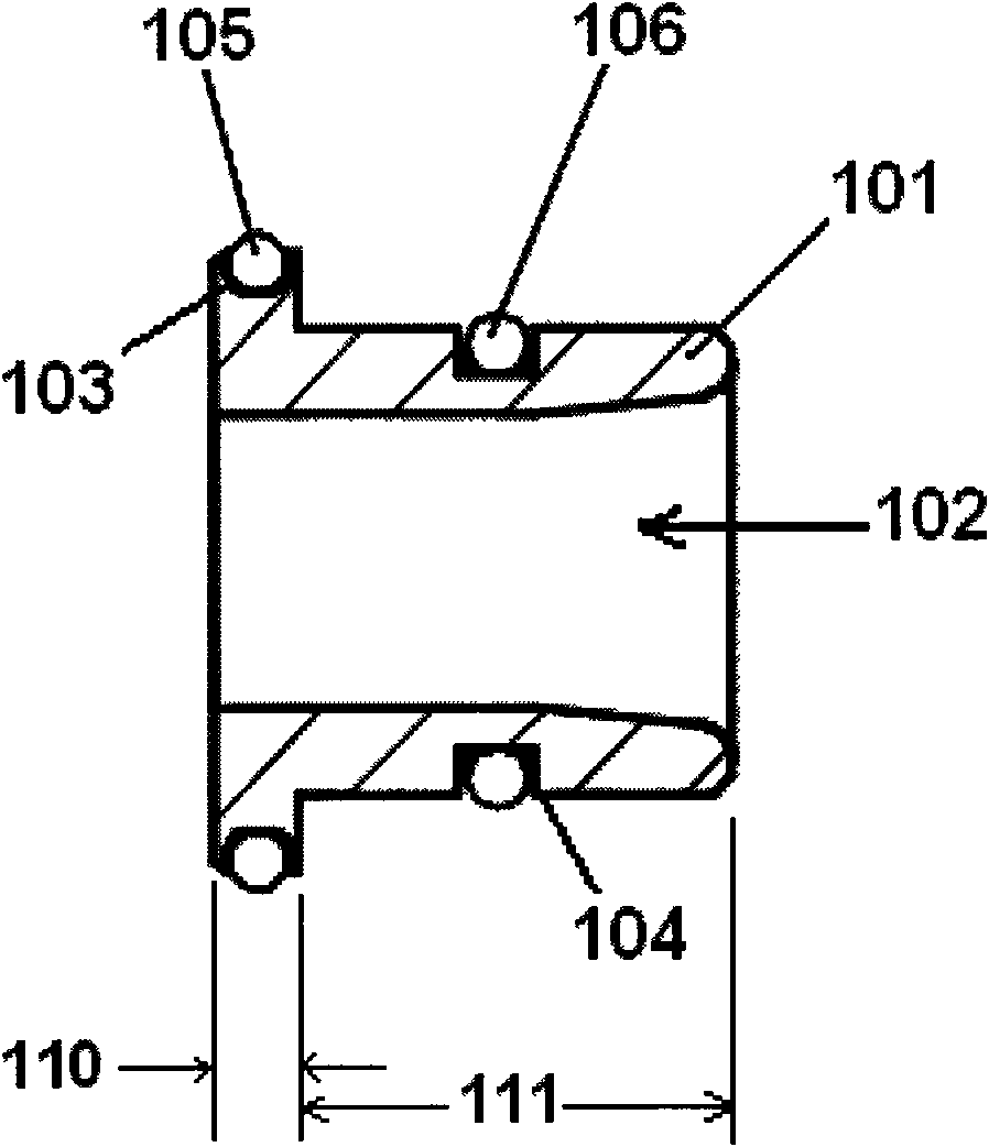
[0046] Such as figure 1 A bushing for a pipe joint, comprising a bushing body 101 with an axial channel 102 inside, the bushing body 101 includes a joint connection section 110 for docking with a pipe joint, and a pipe connection section for docking with a pipe 111. A bushing flange is provided on the peripheral outer wall of the joint connection section 110.

[0047] A first O-ring 105 is provided on the joint connection section 110 , and a second O-ring 106 is provided on the pipeline connection section 111 .

[0048] Wherein, the first positioning structure of the first O-ring 105 is provided on the circumferential outer wall of the joint connecting section 110, and the second O-ring is provided on the circumferential outer wall of the pipeline connecting section. The second positioning structure of 106, the first positioning structure is the first groove 103 arranged in the circumferential direction, the second positioning structure is the second groove 104 arranged in th...

Embodiment 2

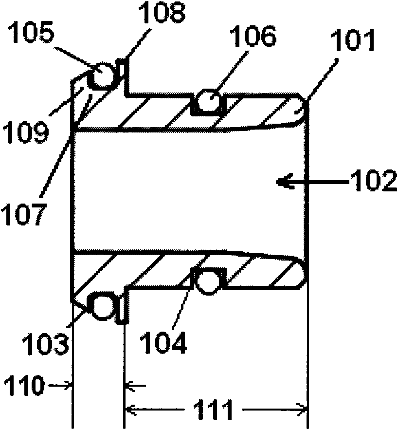
[0053] Such as image 3 A bushing for a pipe joint, comprising a bushing body 101 with an axial channel 102 inside, the bushing body 101 includes a joint connection section 110 for docking with a pipe joint, and a pipe connection section for docking with a pipe 111. A bushing flange is provided on the peripheral outer wall of the joint connection section 110.

[0054] A first O-ring 105 is provided on the joint connection section 110 , and a second O-ring 106 is provided on the pipeline connection section 111 .

[0055] The first positioning structure of the first O-ring 105 is provided on the peripheral outer wall of the joint connection section 110, and the second O-ring 106 is provided on the peripheral outer wall of the pipeline connection section. The second positioning structure, the first positioning structure is the first groove 103 arranged in the circumferential direction, the second positioning structure is the second groove 104 arranged in the circumferential dire...

Embodiment 3

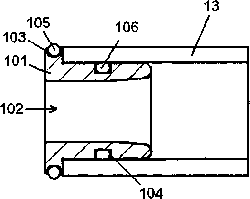
[0059] Such as Figure 5 Pipe fittings shown, including:

[0060] The joint body 1, the interior of the joint body 1 is sequentially arranged along the pipeline insertion direction (direction A):

[0061] Locking cap 5, used to prevent the inner parts from withdrawing;

[0062] The locking cap stopper part 9 is arranged on the pipe insertion end of the joint body, and is used to prevent the locking cap 5 from withdrawing;

[0063] Disassemble the ring 6 to release the locking of the pipeline;

[0064] The snap ring 4 has an annular elastic flange 12 and several latch teeth 10 arranged on the flange 12 for clamping the outer wall of the pipe 13;

[0065] The cone seat 3 is slidingly connected with the inner wall of the joint body 1, and is used to prevent the snap ring 4 from moving in the direction of pipe insertion;

[0066] The cone seat shoulder 8 is provided on the inner wall of the joint body 1, and is used to prevent the cone seat 3 from moving in the direction of pi...


PUM


Abstract

The invention discloses a bushing for a pipe joint. The bushing comprises a bushing body which is provided with an axial channel internally; the bushing body comprises a joint connecting section which is butt joint with the joint body and a pipe connecting section which is butt joint with the pipe; the joint connecting section is provided with a first O-shaped seal ring; the pipe connecting section is provided with a second O-shaped seal ring; the first O-shaped seal ring is used for forming seal connection with the inner wall of the joint body after the butt joint of the joint connecting section and the pipe joint; the second O-shaped ring is used for forming seal connection with the inner wall of the pipe joint in the butt joint of the pipe connecting section and the pipe; the invention also discloses a pipe joint adopting the bushing; and after the liquid is introduced in the pipe, the pipe end surface does not contact with the liquid, thus the pipe joint can not cause harm to the health of people, and has high tightness.

Description

technical field [0001] The invention relates to a pipe connection device, in particular to a bushing for a pipe joint and a pipe joint using the bushing. Background technique [0002] Pipelines are essential infrastructure for industry. The pipeline connection device is an indispensable means of connection. [0003] At present, the well-known pipeline connections mainly include threaded connections and hot-melt connections (PP-R and PE pipes, etc.). The threaded connection is to use the joint and the pipe and its own internal and external threads for screw connection, and use the polytetrafluoroethylene raw material tape as the sealing packing to seal; the hot-melt connection is to use electric heating to heat the connecting part of the pipe and the joint to a molten state , and then pressed against each other, so that the homogeneous materials on the contact surface melt into each other to connect and seal them. The above two connection methods are cumbersome to connect,...

Claims


Application Information

Patent Timeline
Patent Type & Authority Applications(China)
IPC IPC(8): F16L21/00F16L21/08
CPCF16L37/091F16L37/0915
Inventor M·巴克蒂耶里
Owner LA CASA ANGELA HLDG
Why Eureka
Try Eureka