
Ring cooling machine trolley and ring cooling machine with trolley

A technology of ring coolers and trolleys, which is applied in the field of iron and steel smelting, can solve the problems of pressure loss on the lower plate of the trolley, damage to the static sealing device that has not been completely eliminated, and has a large impact, so as to ensure the effect of unloading

Active Publication Date: 2011-07-13
ZHONGYE-CHANGTIAN INT ENG CO LTD
View PDF5 Cites 2 Cited by
  • Summary
  • Abstract
  • Description
  • Claims
  • Application Information

AI Technical Summary

Problems solved by technology

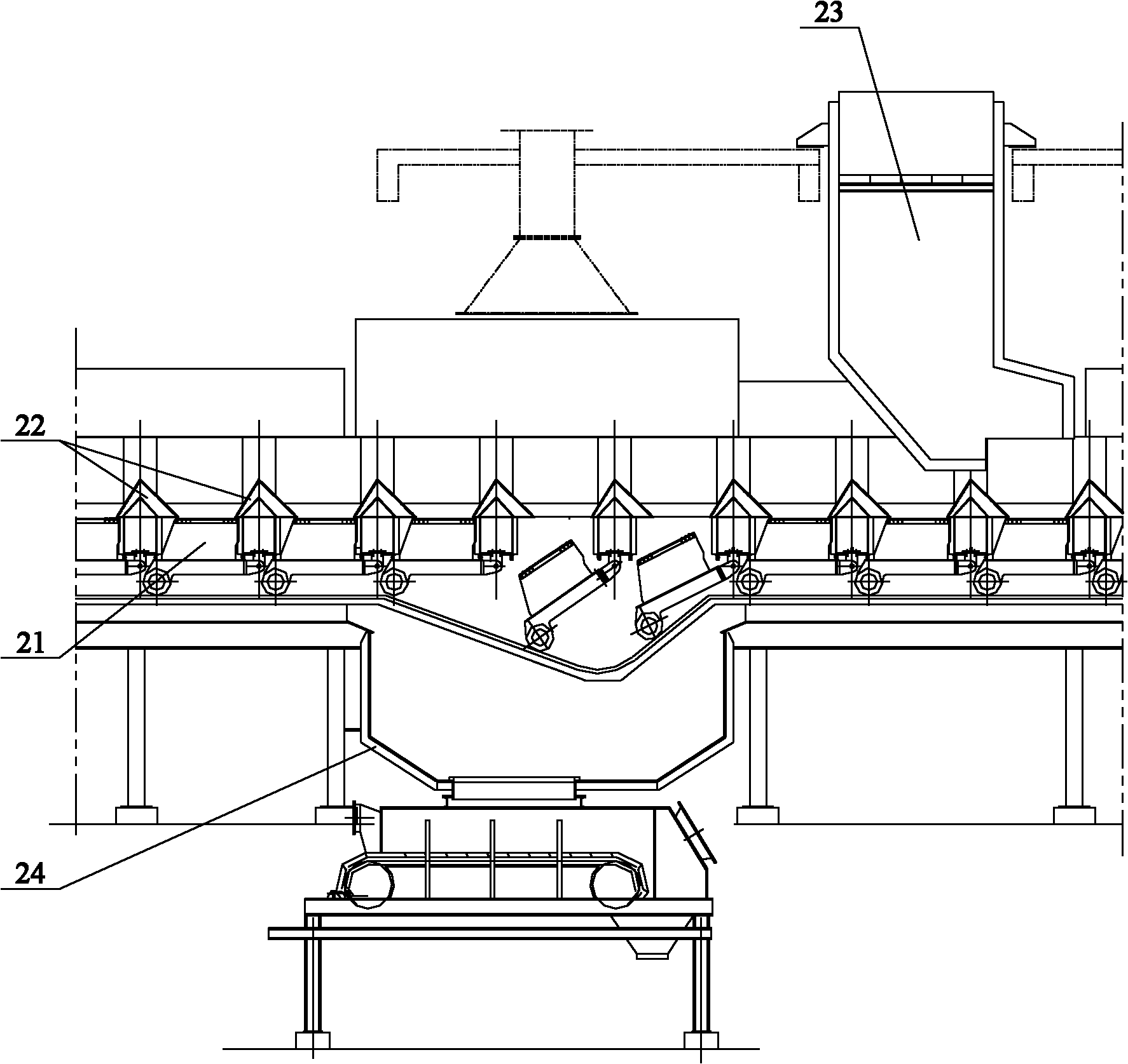
Obviously, when the trolley is unloaded and resumes its position, the mineral material located at the front end of the vertical plate may be sandwiched between the lower plate of the trolley and the static seal of the trolley at the front end of the trolley, damaging the static sealing device of the trolley; Even the lower plate of the trolley is damaged by pressure, causing the welding seam of the trolley to crack and cause permanent deformation, etc.
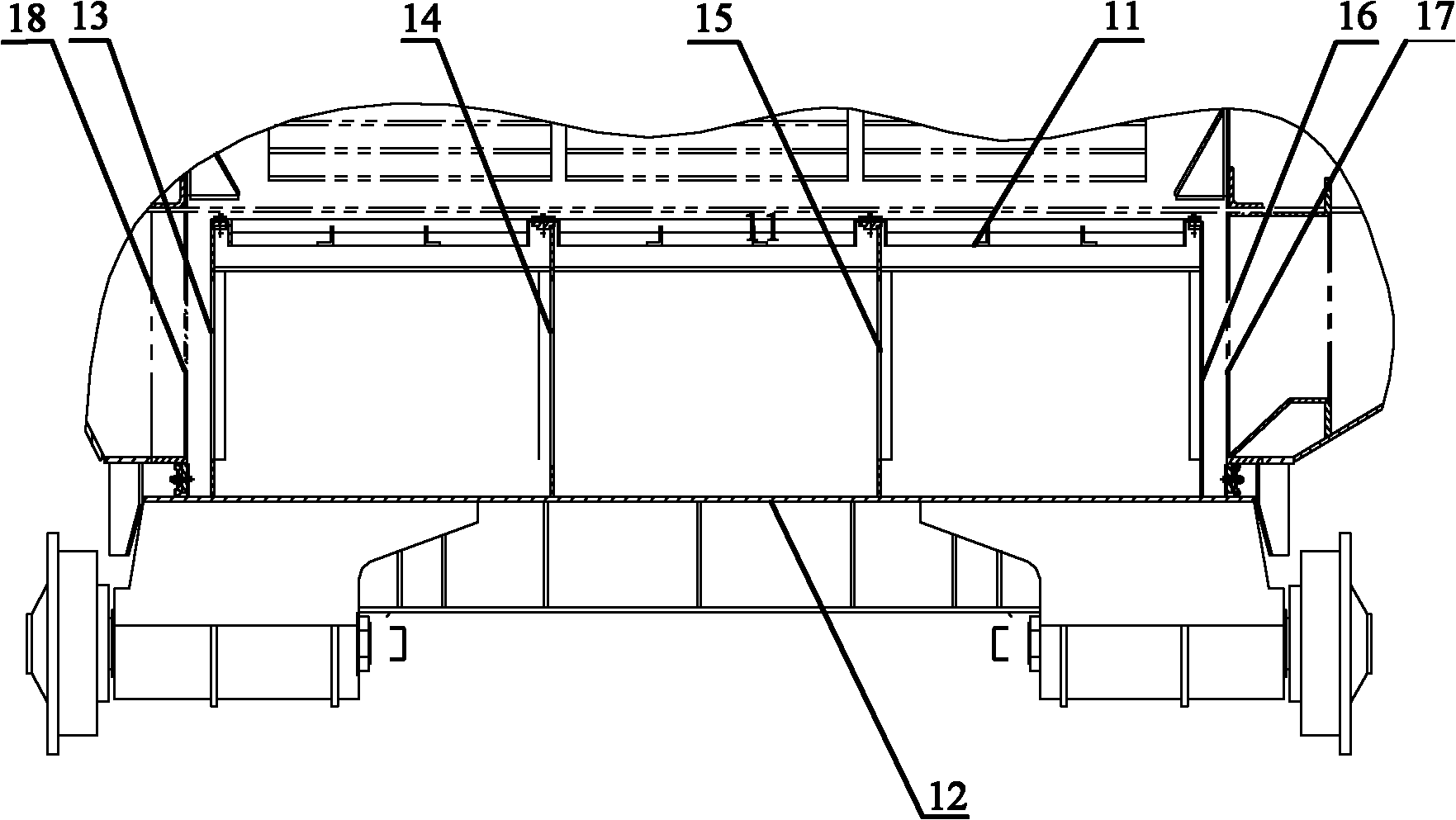
[0007] In particular, the blocking effect of the two vertical plates in the middle has a great influence on the static sealing device near the ball joint seat at the front end of the trolley, and the problem of pressure loss has not been completely solved; The problem of damage to the static sealing device at the inner sealing plate 17 of the trolley and the outer sealing plate 18 of the trolley by the blocking material of the two vertical plates on the side has not been completely eliminated.

Method used


Image

  • Ring cooling machine trolley and ring cooling machine with trolley
  • Ring cooling machine trolley and ring cooling machine with trolley
  • Ring cooling machine trolley and ring cooling machine with trolley

Examples


Embodiment Construction

[0041] The core of the present invention is to provide a ring cooler trolley, which mainly realizes the complete unloading of the lower plate of the trolley through the improved design of the supporting vertical plate and its matching relationship, which can effectively avoid damage caused by material accumulation at the front end of the vertical plate Defects in the static seal of the trolley and the lower plate of the trolley.

[0042] Without loss of generality, this embodiment will be described in detail below in conjunction with the accompanying drawings.

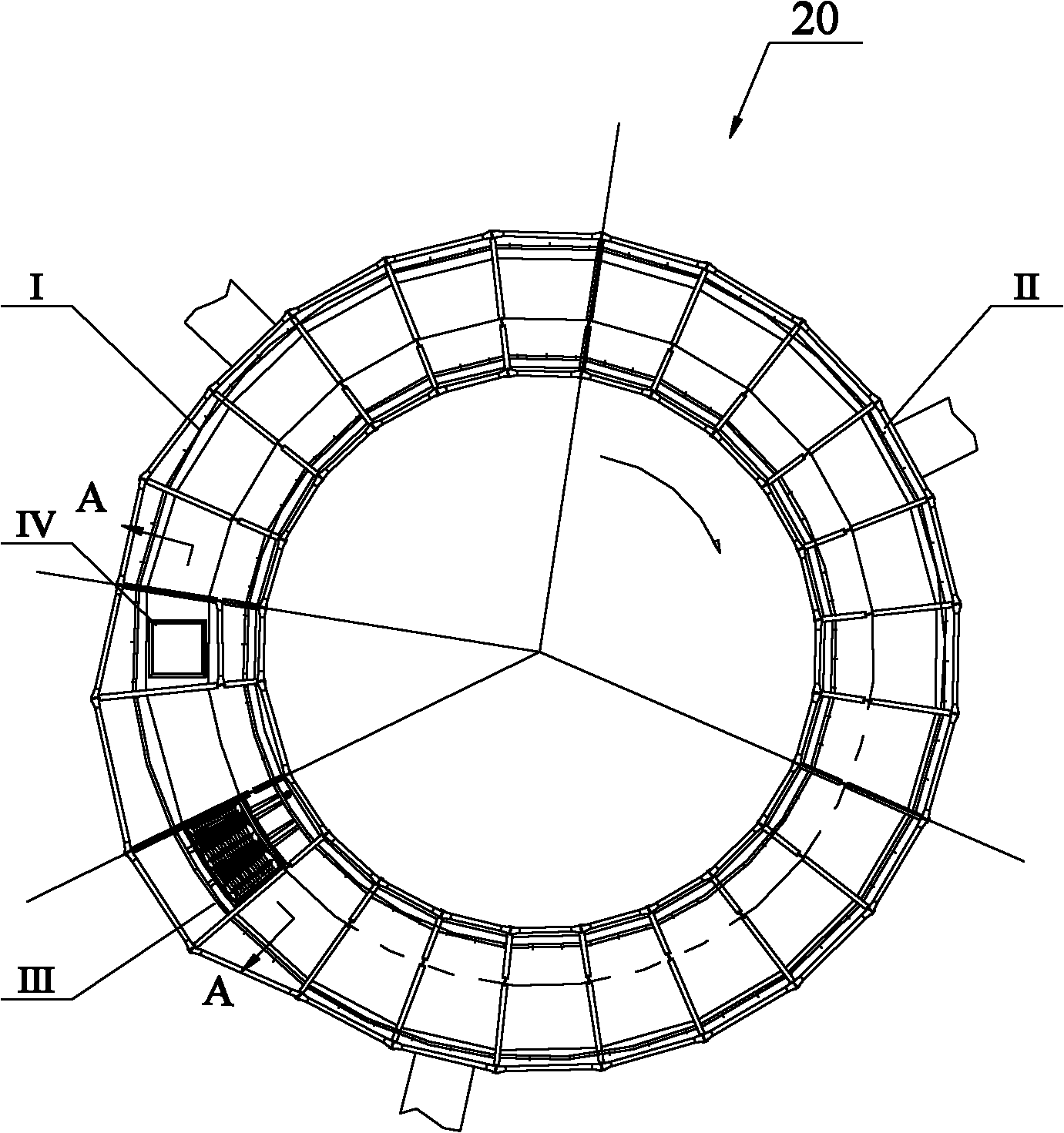
[0043] The inside and outside of the orientation words involved in this article are defined based on the center of the annular cooler, and the front and rear of the orientation words involved are defined based on the rotation direction of the annular cooler. It should be understood that the use of orientation words such as inner, outer, front, and back does not limit the scope of protection claimed in this application. ...


PUM


Abstract

The invention discloses a ring cooling machine trolley. Two vertical support plates vertical to the running radius direction of the ring cooling machine trolley are arranged between a grate plate and a lower flat plate of the ring cooling machine trolley. The bottoms of the preposed ends of the two vertical support plates are provided with a buildup accommodation space respectively. A connecting part is fixedly arranged between the two vertical support plates. A radial distance between the inner vertical support plate and an inner sealing plate of the trolley, the radial distance between the outer vertical support plate and an outer sealing plate of the trolley, a vertical distance between the connecting part and the lower flat plate of the trolley, a peripheral distance between the root part of the buildup accommodation space on each vertical support plate and a static sealing device of a preposed support beam of the trolley, and the height dimension of the buildup accommodation space are all more than a preset distance. The lower flat plate of the trolley can realize smooth discharging in the local area range of the static sealing device of the trolley, and effectively overcomes the shortcoming that the preposed ends of the vertical plates block materials to cause damages to the static sealing and the lower flat plate of the trolley. Based on the ring cooling machine trolley, the invention also provides a ring cooling machine with the trolley.

Description

technical field [0001] The invention relates to the field of iron and steel smelting, in particular to a trolley for an annular cooler and an annular cooler with the trolley. Background technique [0002] Annular coolers are used in iron and steel enterprises to cool sintered high-temperature materials. The annular cooler has a circular shape as a whole, and is divided into a cooling zone and a non-cooling zone along the circumference. During the operation, the ore to be cooled is poured into each ring cooler trolley from the charging station in the non-cooling area, and after entering the cooling area, the ore is cooled by the pressure wind, and then each ring cooler trolley enters the non-cooling machine. The unloading station in the area completes cooling and unloading. [0003] The existing annular cooler trolley has a double-layer structure, the upper layer is a grate layer for carrying materials, and the lower layer is a structural flat layer. The patent document wh...

Claims


Application Information

Patent Timeline
Patent Type & Authority Applications(China)
IPC IPC(8): F27D15/02
Inventor 高德亮戴传德张震
Owner ZHONGYE-CHANGTIAN INT ENG CO LTD
Learn More